Do you have a question about the ALLEN & HEATH GL2800 and is the answer not in the manual?
| Direct Outputs | Yes, on mono channels |
|---|---|
| Effects | None built-in |
| Type | Analog |
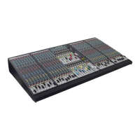
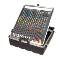
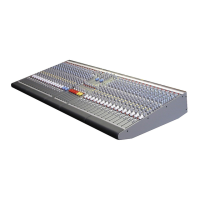
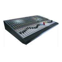
| Channels | 24, 32, or 40 |
| Stereo Channels | 4 |
| EQ | 4-band EQ |
| Phantom Power | +48V globally switchable |
| Dimensions | Varies by model |
| Weight | Varies by model |
| Inputs | Mic/Line inputs on mono channels, stereo line inputs on stereo channels |
| Outputs | Main L/R, Groups, Matrix, Aux |
| Faders | 100mm |
| Auxiliary Sends | 10 aux sends |
| Groups | 8 groups |
| Power Supply | Internal power supply with external backup option |
Covers cautions, risks, grounding, water/moisture, ventilation, heat, servicing, power, and cord routing.
Advice on preventing damage, environmental protection, cleaning, lifting, transport, and hearing protection.
Instructions for replacing the mains plug, including wire colour codes.
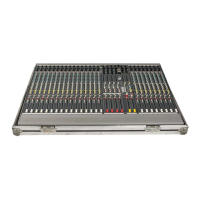
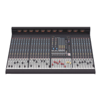
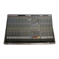
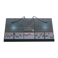
Lists the main capabilities and specifications of the GL2800 console.
Advice on console placement, ventilation, and avoiding electromagnetic interference.
Instructions for connecting the console's power supply unit (RPS11).
Information on connecting an optional backup power supply for redundancy.
Importance of grounding for safety and audio performance to prevent shock and hum.
Explains common audio connectors and their wiring for the console.
Details on Mono/Stereo MIC/LINE IN, MIC OUT, INSERT, DIRECT OUT, STEREO RETURN, and TB/GEN OUT.
Explains FOH mode (groups/LR main) and Monitor mode (auxes main, M engineer's wedge).
Explains MIC INPUT, STEREO LINE INPUT, EQ, AUX SENDS, BAL, MUTE, PFL, METER, ROUTING, and FADER.
Covers ST1, ST2 INPUTS, AUX SENDS, MUTE, PFL, ROUTING, and FADER.
Details AUX MASTERS, AUX AFL, REV mode, GRP to LR/M, PAN, MUTE, and GROUP AFL/FADER.
Covers AUX 9-10 MASTER, REV mode, AUX MUTE, LR to M, METERS, LR MASTERS, M MASTER, and WEDGE mode.
Explains EXT IN, GRP 1-8, L,R,M inputs and LEVEL, MUTE controls for the matrix.
Covers console monitor, headphone sockets, stereo monitoring, and monitor selection.
Explains TALKBACK enable, TALK latch mode, and SIGNAL GENERATOR controls.
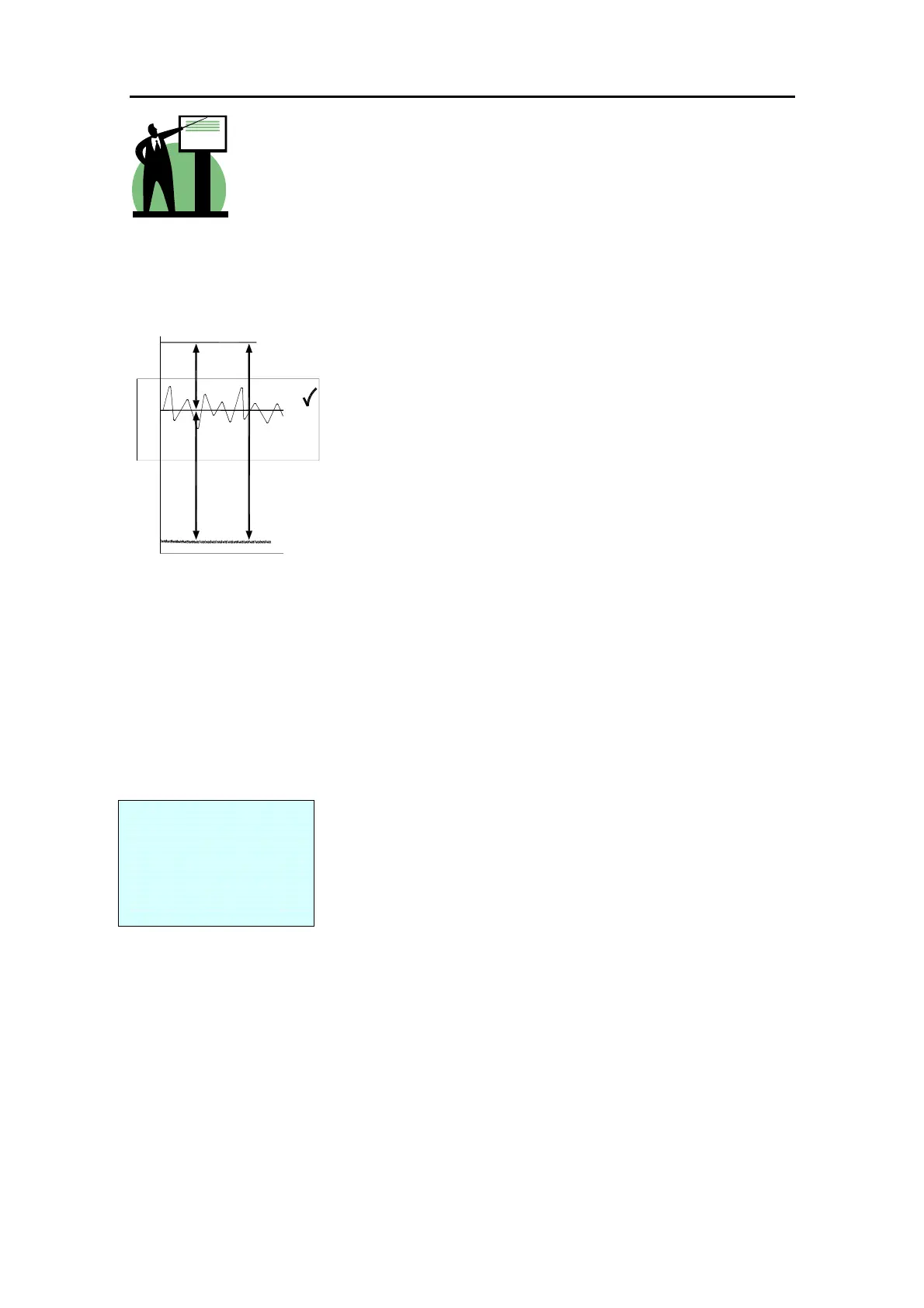
Detailed explanation of signal gain matching for optimal performance and dynamic range.
Details the key differences in operation and control routing between FOH and Monitor modes.
Covers mono recording, stereo recording, remote broadcast, zone feeds, delay fill speakers, and hearing assist.
How to create IEM mixes with ambience and set up for recording with GL2800.
How to configure aux sends as pre or post fader for different routing needs.
Methods for driving PA sub-bass speakers with dedicated mixes.
How to use direct outputs for recording or monitor sends.
Details on the unique flexibility of full-feature stereo channels and their configurations.
How to use mute groups for simultaneous channel muting.
Detailed electrical performance metrics including input/output levels, noise, and EQ.
Physical dimensions, weight, and model variations of the GL2800.
Summary of input/output connections, specifications, and part numbers for accessories.
Steps for accessing and configuring internal jumpers for alternative settings.
Details on specific internal jumper settings for Aux pre/post EQ, direct output, and channel aux settings.
Configuration for Talkback mic +48V and return aux pre/post settings.