GR1
USER GUIDE
11
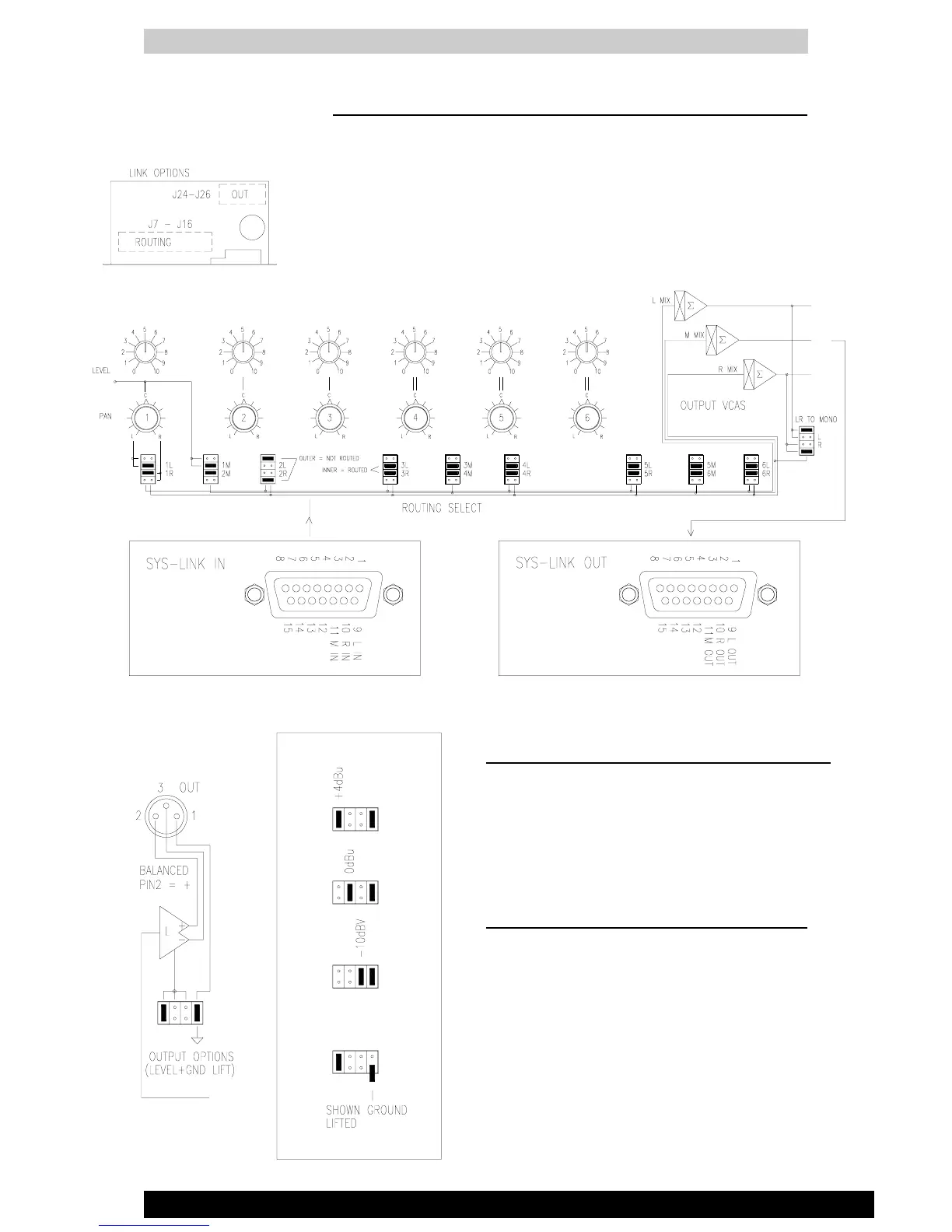
ROUTING THE CHANNELS TO THE OUTPUTS
Each of the 6 channels may be routed as required to a combination of the 3 outputs
L, R and M to feed up to 3 mono zones or one stereo and one mono zone. The L
and R post level outputs may also be routed to the M output for situations where a
L+R sum is required. Note that the channel inputs may be summed with L+R to
provide an independent mix based on the L and R outputs.
OPTION LINKS - CHANNEL ROUTING
Select the inner jumper links for routed signals, outer links for not routed.
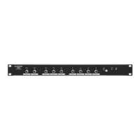
MAIN OUTPUTS
The main L, R and M outputs are available on electroni-
cally balanced line level 3-pin XLR male connectors.
OPTION LINKS - LINE OUTPUT LEVEL
These may be individually set for one of three standard
operating levels by positioning the jumper links as
shown. +4dBu (1.2Vrms) High level
0dBu (0.775Vrms) Line level
-10dBV (300mVrms) Low level
OPTION LINKS - OUTPUT XLR GROUND LIFT
Set the jumper as shown to connect or disable XLR pin
1 from audio 0V for optimum system grounding to avoid
problems with ground loops.
L,R,M SYS-LINK INPUTS/OUTPUTS
The L, R and M outputs are also available on the SYS-LINK
OUT connector. Inputs are available on the SYS-LINK IN
connector. These operate unbalanced at -2dBu (600mVrms)
and may be used as additional mix inputs and outputs or to
expand the system using SYS-LINK.
 Loading...