1336 PLUS II Firmware Download Module 3
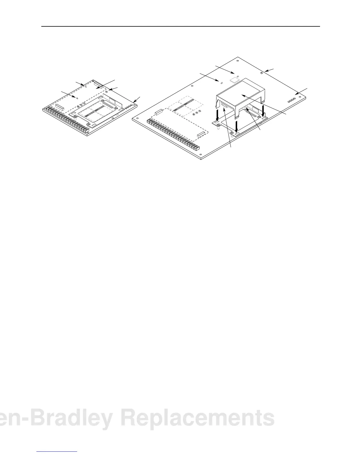
Figure 1
Component Locations
5. Install the Flash Download Module in the Main Control Board
cradle – place the guide tab into the slot, making sure the module
connector lines up with the connector on the Main Control Board.
Press the module until the 4 locking tabs lock in place.
6. Connect the communications cable (refer to page 1) between the
9 pin D-Shell Communications Connector on the Flash
Download Module and the selected computer COM port.
7. Apply power using one of the methods described on page 2.
When power is applied, the POWER SUPPLY and STOP status
LEDs on the Main Control Board should illuminate. If an
external power supply is used, the FAULT LED may also be
illuminated.
Obtaining the Files Copying the Files to the Computer
8. This procedure assumes that you are using Windows
95. The
procedure may vary if a different computer/operating system is
used.
A. If you obtained the file on a floppy disk, verify that you have
the correct file using the information in step C. Then proceed
to step 9.
B. Using an Internet browser such as Netscape Navigator
or
Microsoft
Internet Explorer, access the 1336 PLUS II
download page on the World Wide Web at:
http://www.ab.com/drives
then select . . .
“
Software
” followed by . . .
“
Flash ROM Updates
”
The files available for downloading will be listed.
Frames A1 - A4
Frames B - G
J20
J14
Spare Jumpers
Status LEDs
Status LEDs
Spare Jumpers
Flash
Download Module
External Power Connector
Communications Connector
Control Interface Option Location
J20
J14
ANALOG I/O
SLOT B
8642
7531
J10
ANALOG I/O
SLOT A
86
7531
J9
POWER
SUPPLY
RUN
STOP
FAULT
POWER
SUPPLY
RUN
STOP
FAULT
ANALOG I/O
SLOT B
8642
7531
J10
ANALOG I/O
SLOT A
86
7531
J9
Allen-Bradley Replacements
 Loading...


