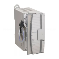
2 1336 PLUS II Firmware Download Module
Main Control Board Power
Requirements
In order to upgrade firmware, the Main Control Board must have
power applied. This can be accomplished through one of the
following methods:
• Application of AC line voltage per instructions in Chapter 2 of
the 1336
PLUS II User Manual. This is the normal method for
installed drives.
• External power supply through the auxiliary 24V DC input at
terminal block TB4 (B frame & up, see Auxiliary Inputs – TB4,
TB6 in the User Manual).
• External power supply through power connector on module (all
drives). This method does not power the entire logic section, but
provides enough power to activate the flash memory. This is the
best method for drives not yet installed. The external supply must
provide 6.0 - 9.0V DC, 0.5A and is connected on the right-side of
the module (see Figure 1).
Important:
Do Not apply power until instructed to do so.
Installation Procedure Important:
During the time that the flash memory is being upgraded,
the drive will be in a “non-operational state” and will not
havetheabilitytocontrolthemotor.Becertainthatplacing
the drive in a non-operational state is acceptable.
1. Remove and lock-out all incoming power to the drive.
2. If a HIM (or other snap-in module) is installed, remove it by
carefully squeezing the locking tabs-in and pulling-out.
3. A Frame Drives - If a Control Interface Board (L option) is
installed, carefully remove the board by loosening the 2 captive
screws. Position the board and attached wires off to the side of the
chassis.
4. Locate a spare jumper on the Main Control Board and install it at
J20 (see Figure 1). This jumper allows the flash EEPROM to be
overwritten with a new version of firmware.
!
ATTENTION: This drive and module contain ESD
(Electrostatic Discharge) sensitive parts and assemblies.
Static control precautions are required when installing,
testing, servicing or repairing this assembly. Component
damage may result if ESD control procedures are not
followed. If you are not familiar with static control
procedures, reference publication 8000-4.5.2, “Guarding
AgainstElectrostaticDamage”oranyotherapplicableESD
protection handbook.
!
ATTENTION: To avoid a shock hazard, assure that all
power to the drive has been removed before proceeding. In
addition, verify that the DC bus has discharged by
measuring across the “+DC” and “–DC” terminals of TB1
with a voltmeter. The voltage should be 0.0VDC.

 Loading...


