Publication 1398-5.1 — January 2000
Wire the ULTRA Plus PDM Components 3-43
Operator Terminal (screw terminal on back) .
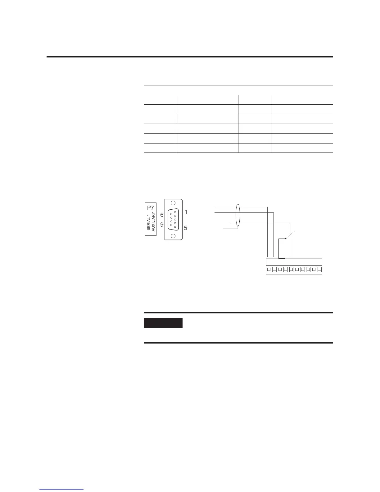
Figure 3.27
ULTRA Plus PDM connects to the Operator Terminal
Pin and Signal names
Pin RS-232 Pin RS-422
1Tx 6TxA
2RxD 7TxB
3RTS 8RxA
4CTS 9RxB
5 Common 10 Common
IMPORTANT
$MXPSHUFXVWRPHUVXSSOLHGPXVWEHLQVWDOOHGEHWZHHQ
SLQVDQGRIWKH8/75$3OXV2SHUDWRU7HUPLQDOIRU
56RSHUDWLRQ
1
2
3 TxD
4
5 COMMON
6 SHIELD
7
8
9
RxD
Pin
1234 56 78910
Tx
Rx
RTS
CTS
COMMON
TxA
TxB
RxA
RxB
COMMON
ULTRA Plus
Positioning Drive Module
(1398-PDM)
ULTRA Plus
Operator Terminal
(1398-HMI-003)
JUMPER
customer supplied
jumper
9101-2205-XXX
ULTRA Plus to 1398-HMI-003
ULTRA Plus Operator Terminal cable

 Loading...


