Rockwell Automation Publication 1769-UM021G-EN-P - October 2015 305
Appendix A
Troubleshoot the Module
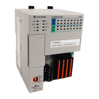
This section explains how to interpret the status indicators on your
CompactLogix™ 5370 controllers. All controllers use the status indicators that are
described in the following table.
Use Logix Designer
Application for
Troubleshooting
The Logix Designer application indicates fault conditions in the following ways:
Warning signal on the main screen next to the module - This occurs when the
connection to the module is broken. The controller state also indicates Faulted
and the Controller fault is illuminated in red.
Status Indicator Description
RUN Indicates the operating mode of the controller.
FORCE Indicates the force state.
I/O Indicates the current state of communication between the controller and I/O modules.
OK Indicates the state of the controller.
NS Indicates the EtherNet/IP network status regarding the controller operating on the
network.
LINK 1 Indicates the EtherNet/IP link status for port 1 if the controller.
LINK 2 Indicates the EtherNet/IP link status for port 2 of the controller.
SD Indicates if there is activity on the SD card.

 Loading...


