Rockwell Automation Publication 1794-IN102D-EN-P - July 2018 7
FLEX I/O AC Digital Input Modules
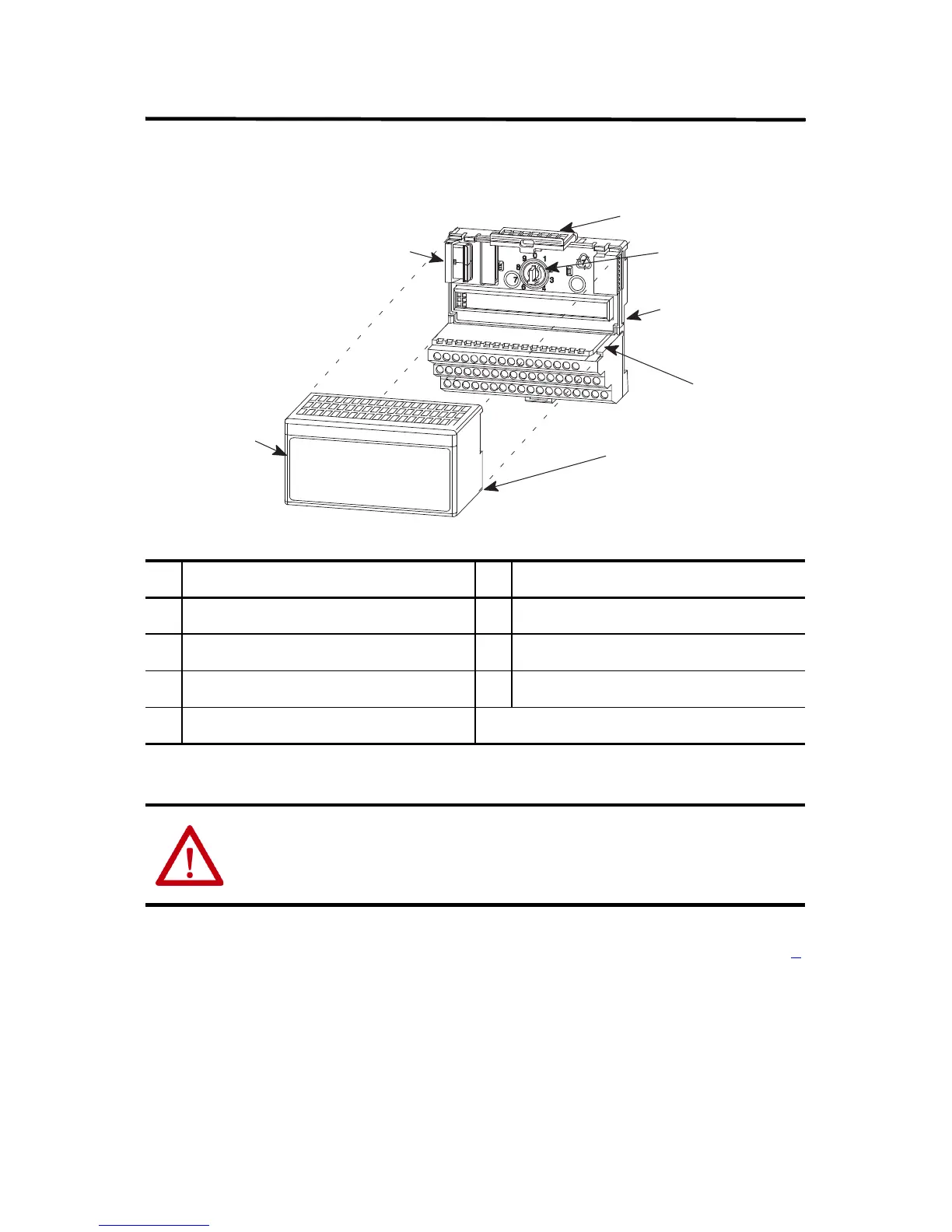
Installing Your AC Digital Input Module
The module mounts on a 1794 terminal base.
1. Rotate the keyswitch (1) on the terminal base (2) clockwise to position 8
as required for this type of module.
2. Ensure that the Flexbus connector (3) is pushed all the way to the left to
connect with the neighboring terminal base/adapter. Yo u c ann o t in s t a l l
the module unless the connector is fully extended.
Description Description
1Keyswitch 5Alignment bar
2Terminal base 6Groove
3 Flexbus connector 7 Latching mechanism
4Module
ATTENTION: During mounting of all devices, be sure that all debris (metal chips,
wire strands, etc.) is kept from falling into the module. Debris that falls into the
module could cause damage on power up.
1
2
3
4
5
6
7

 Loading...


