14 FLEX I/O Digital Input Modules
Publication 1794-IN093E-EN-P - August 2018
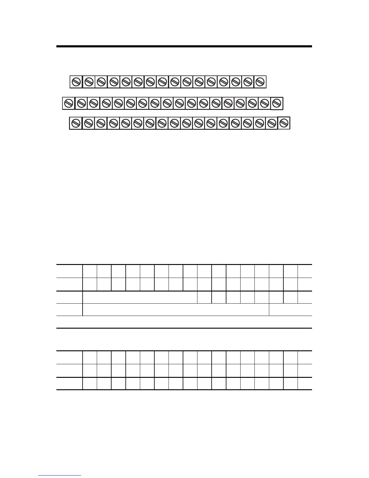
1794-TB32 and 1794-TB32S Terminal Base Wiring for 1794-IB32
Configure Your Input Module
Configure your input module by setting bits in the configuration word (write word).
Image Table Memory Map for the 1794-IB8 Module
Dec 1514131211109876543210
Oct 17161514131211107 6 5 4 3 2 1 0
Read 1 Not used I7 I6 I5 I4 I3 I2 I1 I0
Write 1 Not used Input Filter 0...7
Where I = Input
Image Table Memory Map for the 1794-IB16 Module
Dec 1514131211109876543210
Oct 17161514131211107 6 5 4 3 2 1 0
Read 1 I15I14I13I12I11I10I9I8I7I6I5I4I3I2I1I0
+V1 COM1
17 18 19 20 21 22 23 24 25 26 27 28 29 30 31 32 33
0 1 2 3 4 5 6 7 8 9 10 11 12 13 14 15
16
35 36 37 38 39 40 41 42 43 44 45 46 47 48 49 50 51
34
NC
+V2 = Terminals 43, 45, 47, and 49
Inputs
+V1 COM1 +V1 COM1 +V1 COM1 +V2 COM2 +V2 COM2 +V2 COM2 +V2 COM2 NC
+V1 = Terminals 35, 37, 39, and 41
COM1 = Terminals 36, 38, 40, and 42
NC = No connections (terminals 16, 33, 34, and 51)
COM2 = Terminals 44, 46, 48, and 50
NC
NC
(1794-TB32 shown)
Inputs
 Loading...


