90 Rockwell Automation Publication 2094-UM001J-EN-P - March 2017
Chapter 5 Connect the Kinetix 6000 Drive System
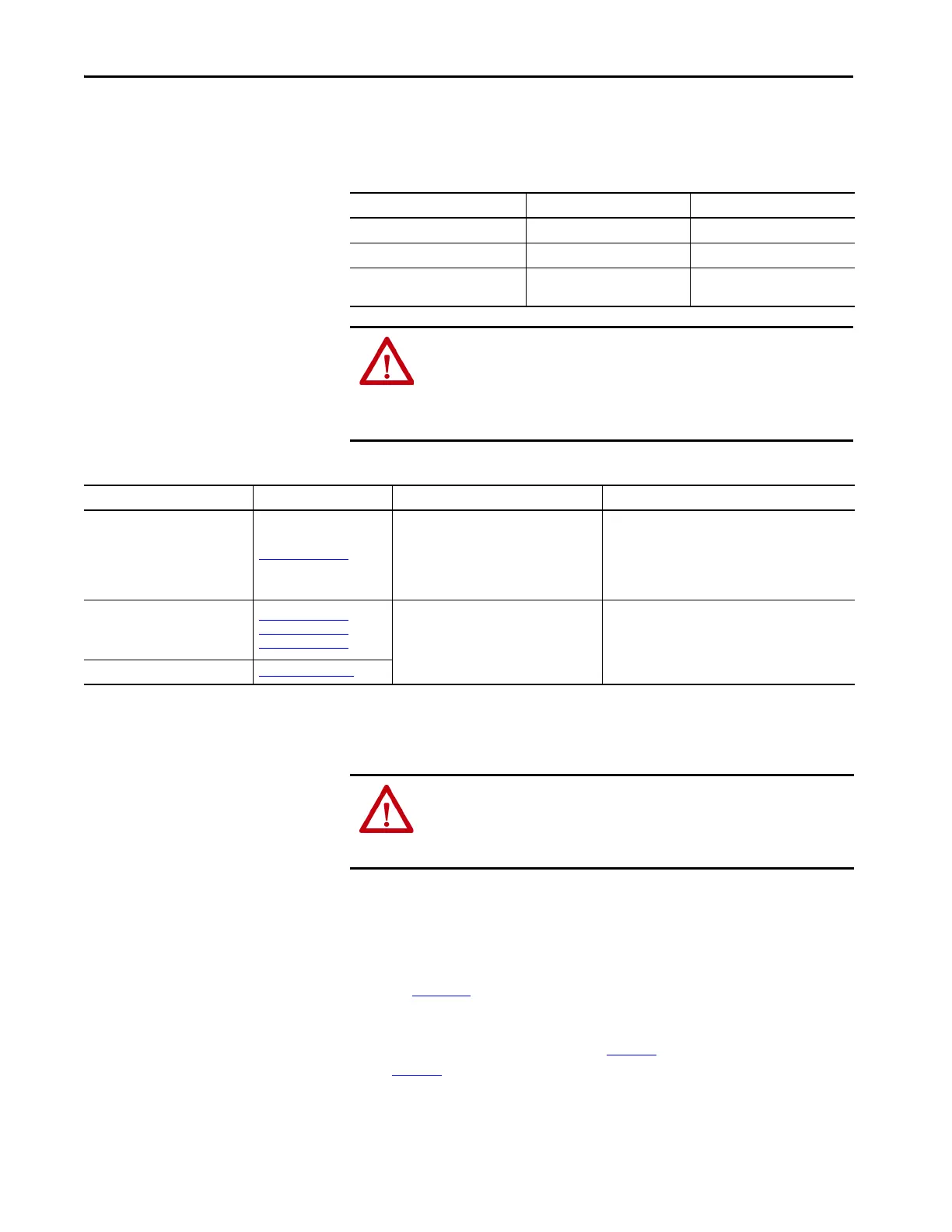
When using ungrounded input power in common-bus configurations, use this
table to determine where to set the ground jumper.
Table 58 - Ground Jumper to Set
Table 59 - Ground Jumper Configurations
Set the Ground Jumper
Follow these steps to set the ground jumper for ungrounded power.
1. Remove the IAM module from the power rail.
For detailed instructions, refer to Remove Kinetix 6000 Drive Modules
on page 182
.
2. Remove the top and bottom front-panel screws.
Refer to the figures beginning on page 92
(230V IAM module) or
page 93
(460V IAM module) for an illustration of your actual hardware.
Leader Drive Follower Drive Set the Jumper in This Drive
Kinetix 6000 IAM module Kinetix 6000 IAM module Leader drive
Kinetix 6000 IAM module Non-Kinetix 6000 drive Leader drive
Non-Kinetix 6000 drive Kinetix 6000 IAM module
Follower drive (if no setting exists
in the leader drive)
ATTENTION: Risk of equipment damage exists. The facility ground
configuration must be accurately determined. Do not move the ground
jumper for grounded power configurations (default). Move the ground
jumper for ungrounded, corner-grounded, and impedance-grounded power,
or when an active converter supplies the DC-bus voltage.
Ground Configuration Example Diagram Ground Jumper Configuration Benefits of Correct Configuration
Grounded (wye) Figure 39 on page 85
Grounded power (default setting)
• UL and EMC compliance
• Reduced electrical noise
• Most stable operation
• Reduced voltage stress on components and motor
bearings
• AC-fed ungrounded
• Corner grounded
• Impedance grounded
Figure 42 on page 87
Figure 40 on page 86
Figure 41 on page 86
Set for ungrounded power
• Helps avoid severe equipment damage when ground
faults occurs
• Reduced leakage current
DC-bus from active converter Figure 92 on page 196
ATTENTION: To avoid personal injury, the ground jumper access area must
be kept closed when power is applied. If power was present and then
removed, wait at least 5 minutes for the DC-bus voltage to dissipate and
verify that no DC-bus voltage exists before accessing the ground jumper.
 Loading...

