94 Rockwell Automation Publication 22C-UM001J-EN-E - January 2017
Chapter 3 Programming and Parameters
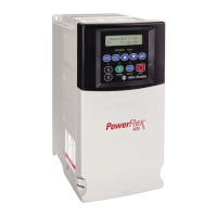
A191 [Skip Freq Band 2] Related Parameter(s): A190
Determines the bandwidth around A190 [Skip Frequency 2]. A191 [Skip Freq Band 2] is split applying 1/2 above and 1/2 below the actual skip frequency.
A setting of 0.0 disables this parameter.
Values Default: 0 Hz
Min/Max: 0.0/30.0 Hz
Display: 0.1 Hz
Frequency
Time
Skip Frequency
Command
Frequency
Drive Output
Frequency
Skip Frequency Band
A192 [Skip Frequency 3] Related Parameter(s): A193
Sets the frequency at which the drive will not operate.
A setting of 0 disables this parameter.
Values Default: 0 Hz
Min/Max: 0/320 Hz
Display: 1 Hz
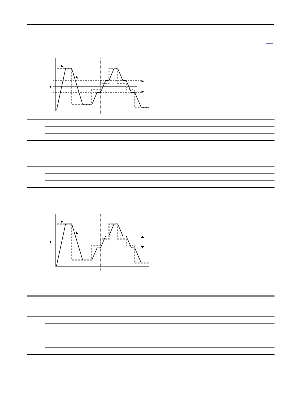
A193 [Skip Freq Band 3] Related Parameter(s): A192
Determines the bandwidth around A192 [Skip Frequency 3]. A193 [Skip Freq Band 3] is split applying 1/2 above and 1/2 below the actual skip frequency.
A setting of 0.0 disables this parameter.
Values Default: 0 Hz
Min/Max: 0.0/30.0 Hz
Display: 0.1 Hz
Frequency
Time
Skip Frequency
Command
Frequency
Drive Output
Frequency
Skip Frequency Band
A194 [Compensation]
Enables/disables correction options that may improve problems with motor instability.
Options 0“Disabled”
1 “Electrical” (Default)
(1)
Some drive/motor combinations have inherent instabilities which are exhibited as non-sinusodial motor currents. This setting
attempts to correct this condition.
2 “Mechanical” Some motor/load combinations have mechanical resonances which can be excited by the drive current regulator. This
setting slows down the current regulator response and attempts to correct this condition.
3“Both”
(1)
(1) Use “Dead Time Compensation” algorithm to minimize flat spots in motor current waveforms. Use this solution also to achieve motor stability.
 Loading...