Rockwell Automation Publication 22C-UM001J-EN-E - January 2017 39
Installation/Wiring Chapter 1
Wiring terminations on the master controller will vary depending on the
master controller used and “TxRxD+” and “TxRxD-” are shown for
illustration purposes only. Refer to the master controller’s user manual for
network terminations. Note that there is no standard for the “+” and “-” wires,
and consequently Modbus device manufacturers interpret them differently. If
you have problems with initially establishing communications, try swapping
the two network wires at the master controller.
On Drive Connections
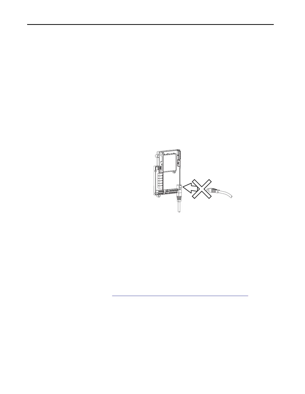
PowerFlex 400 Frame D, E, F, G and H drives are equipped with two RS485
(DSI) ports. One is accessible via an access door when the cover is on and one is
only accessible with the cover off. When one of these ports has a Rockwell DSI
device connected, the second port cannot be used.
Figure 13 - Frame D, E, F, G and H RS485 Ports
EMC Instructions
CE Conformity
Conformity with the Low Voltage (LV) Directive and Electromagnetic
Compatibility (EMC) Directive has been demonstrated using harmonized
European Norm (EN) standards published in the Official Journal of the
European Communities. PowerFlex Drives comply with the EN standards
listed below when installed according to the User Manual.
CE Declarations of Conformity are available online at:
http://www.rockwellautomation.com/certification/overview.page
.
Low Voltage Directive (2014/35/EU)
• EN 61800-5-1 Electronic equipment for use in power installations.
EMC Directive (2014/30/EU)
• EN61800-3 Adjustable speed electrical power drive systems Part 3:
EMC product standard including specific test methods.
RS485 (DSI) Network Connection
Second RS485 (DSI) Connection
 Loading...