ControlNet PLC-5 Hot Backup System 3
Publication 1785-10.8 - October 1998
Installing The Hardware
Follow these steps to install the required hardware for your backup system.
1. Set the ControlNet node address numbers for each of the PLC-5
processors.
The addresses must be consecutive, with the lower number being odd.
For example, a valid node address pair is 1 and 2. You can set the
ControlNet node address via the rotary switches on the top of each
processor.
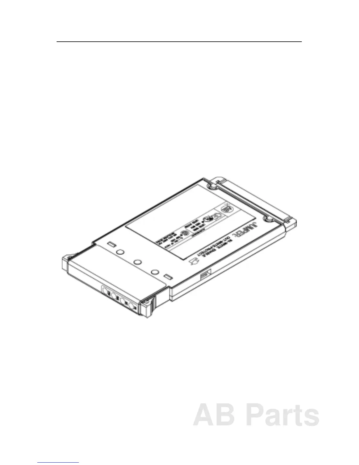
2. Insert the ControlNet backup cartridge into the EEPROM slot of each
PLC-5 processor.
Note: If the ControlNet backup cartridge is not inserted into the
PLC-5 processor, that processor will operate as a normal, standalone
processor, and will not exhibit any of the necessary backup functions.
3. Install each PLC-5 processor into a separate 1771 chassis.
4. Install a power supply for each chassis, and connect to ac power.
5. Wire the ControlNet network to the PLC-5 processors and to the I/O
adapters being used for the backup system.
The network cabling may consist of single or redundant channels.
AB Parts

 Loading...


