Rockwell Automation Publication 5094-IN001B-EN-P - May 2018 13
FLEX 5000 EtherNet/IP Adapters with RJ45 Ports
Power the Adapter
Once you have installed the end anchors and the modules are held firmly in position on the DIN rail, turn on power to the Power RTB.
Remove or Replace the Adapter
1. Turn off power to the Power RTB.
2. If there are I/O modules installed, remove the I/O module from the terminal base next to the adapter. For more information on how to
remove FLEX 5000 I/O modules, see the installation instructions available with each FLEX 5000 I/O module catalog number.
3. Remove all network cables from the adapter.
4. Pull the lever of the Power RTB and then gently pull the Power RTB off the adapter.
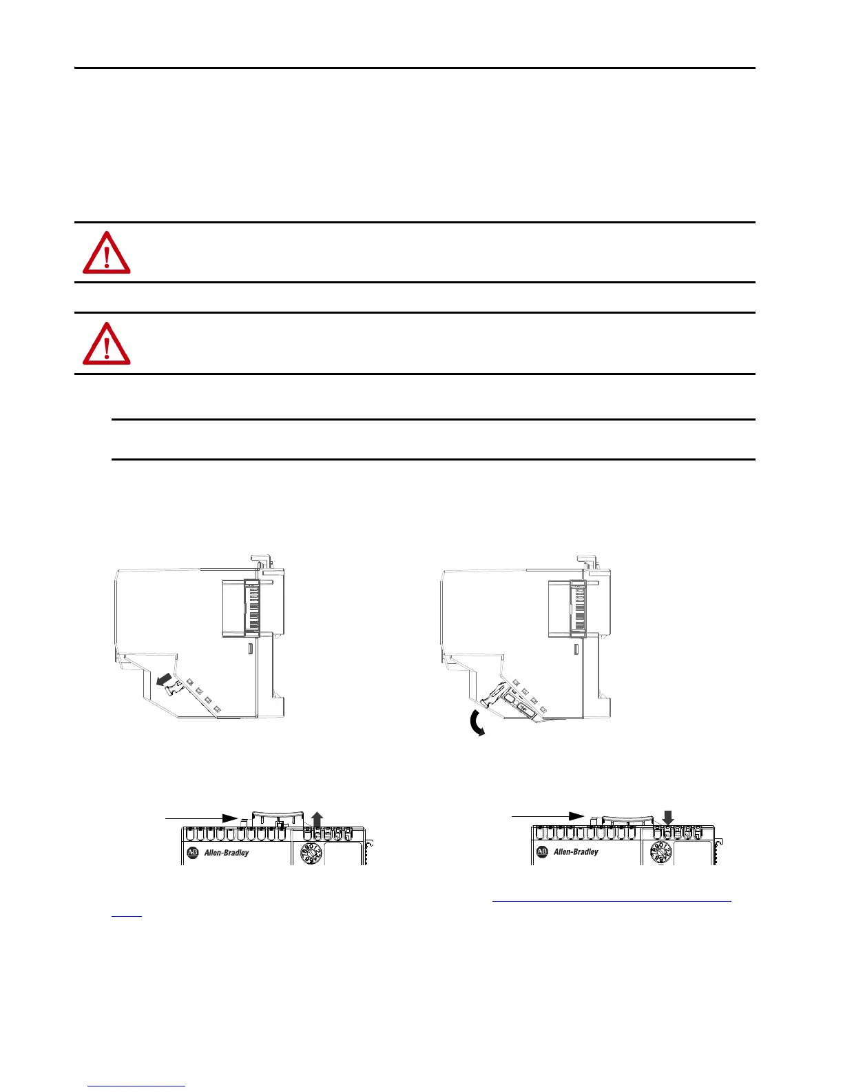
5. Press down the DIN rail latch.
A click indicates that the DIN rail latch is unlocked.
6. Pull the adapter off the DIN rail.
7. To replace the adapter, repeat the installation steps that are described beginning at Set the Network Internet Protocol (IP) Address
on
page 7.
ATTENTION: Do not remove or replace the adapter while power is applied. Interruption of the backplane can result in unintentional operation or
machine motion.
WARNING: If you insert or remove the adapter module while power is on, an electric arc can occur. This could cause an explosion in hazardous location
installations. The module does not support “removal and insertion under power” (RIUP) capability. Do not connect or disconnect the module while power is
applied. Be sure that power is removed before proceeding.
IMPORTANT When you remove power from a FLEX 5000 EtherNet/IP adapter, you shut down power to all installed FLEX 5000 I/O modules. That is, all
system-side power is removed.
EtherNet/IP
™
Adapter
FLEX 5000
TM
I/O
X100
EtherNet/IP
™
Adapter
FLEX 5000
TM
I/O
X100
Locked position
Unlocked position

 Loading...


