12 Rockwell Automation Publication 1794-IN099D-EN-P - November 2018
FLEX I/O DeviceNet Adapter Module
2. Insert connector into mating connector on the DeviceNet adapter module.
3. Connect +V DC power to the left side of the lower connector,
terminal E.
4. Connect -V common to the left side of the upper connector, terminal D.
5. Connections G and F are used to pass +V DC power (G) and -V
common (F) to the next module in the series (if required).
NOTE: Cable colors are shown on the wiring label on the front of the
adapter module.
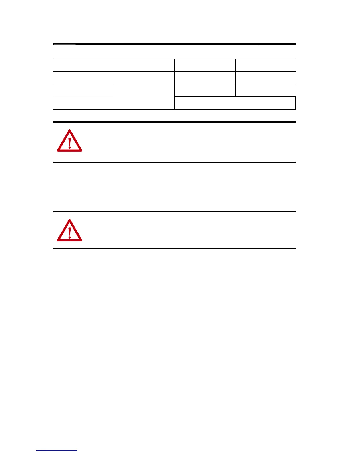
Connect To
BLK wire -V WHT wire CAN high
BLU wire CAN* low RED wire +V
Bare wire Drain * CAN = Controller Area Network
ATTENTION:
• When connecting wiring, torque terminal screws D, E, F, and G to 0.8 N•m (7 lb-in).
• Do not wire more than 2 conductors on any single terminal.
ATTENTION: Power wiring must be less than 3 meters (9.8 ft) in length.
 Loading...


