Rockwell Automation Publication 6000-IN100A-EN-P - August 2020 11
Chapter 1 Drive Mechanical Installation
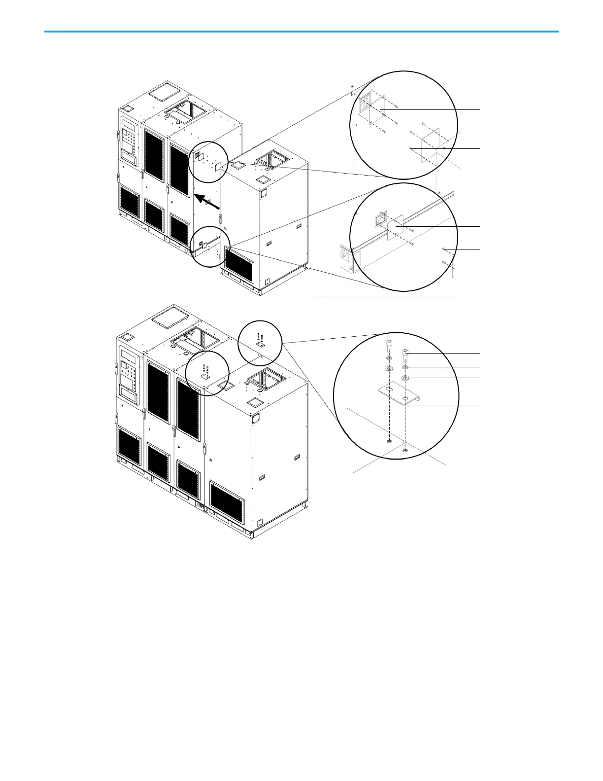
Figure 2 - Secure the Cabinets, A-Frame
Connect Cabinets for B-Frame Drives
The B-Frame for PowerFlex 6000T drives are shipped in two sections, the
Isolation Transformer Cabinet and Power Module/LV Control Cabinet. These
two cabinets must be connected after located in its final position. The cabinets
are connected together in 8 or 10 places (depending on the drive rating), half
along the front edge of the cabinet and half along the rear edge of the cabinet.
Access to the interior of the cabinet is required to make these connections.
Access for the front connections requires only opening the doors. Access for
the rear connections requires removing the back plates of the cabinet.
1. Arrange the sections as directed in the Dimensional Drawings and move
the sections together.
LV cover
M16x16 countersunk
head screw (x4)
Grounding cover
M16x16 countersunk
head screw (x2)
L-shaped bracket (x2)
M12 hexagon socket screw
(x4)
D12 lock washers (x4)
D12 washers (x4)
 Loading...


