38 Rockwell Automation Publication 6000-IN100A-EN-P - August 2020
Chapter 2 Drive Electrical Installation
Electrical Installation
Summary
Connect the System Ground
Cable
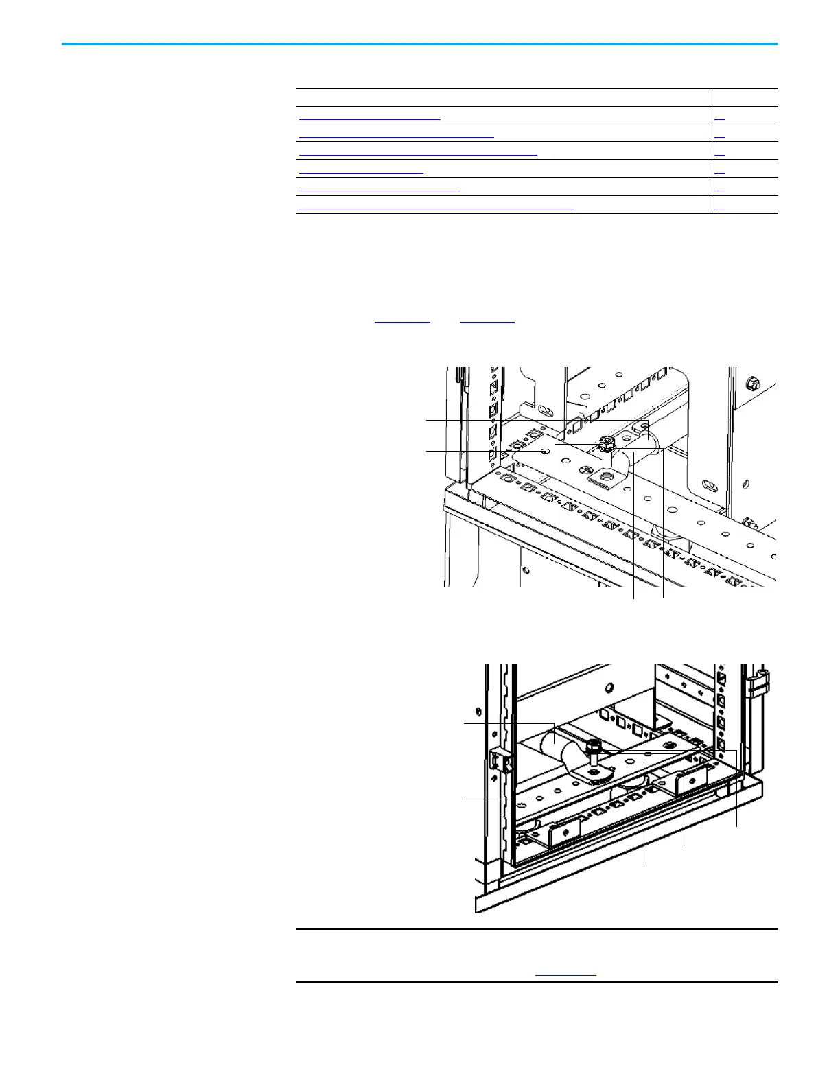
The drive ground bus runs along the bottom of the drive at the front. The
ground bus is accessible at the bottom of the front of each drive cabinet when
the cabinet door is opened. Connect the system ground cable to the drive
ground bus (Figure 16
and Figure 17).
Figure 16 - Ground Cable Connection in the Isolation Transformer Cabinet, A-Frame
Figure 17 - Ground Cable Connection in the Isolation Transformer Cabinet, B-Frame
Connect External Cabling and Wiring Page
Connect the System Ground Cable
38
Insulation Resistance (IR) Test of Power Cables 39
Connect Incoming Line and Outgoing Motor Power Cables 39
Connect Control Power Wiring 42
Connect External Control Signal Wiring 44
Connect Electrical Safety Interlock Circuit to Input Circuit Breaker 45
Customer/Contractor supplied
System Ground cable
Lock washerFlat washerM8x25 bolt
Ground Bus
Customer/Contractor supplied
System Ground cable
Ground Bus
Lock washer
Flat washer
M8x25 bolt
IMPORTANT
If an optional cabinet is supplied, the system ground cable connection is
in the optional cabinet. See the PowerFlex 6000T Drives Hardware
Service Manual, publication 6000-TG100
.
 Loading...


