14 Rockwell Automation Publication 6000-IN100A-EN-P - August 2020
Chapter 1 Drive Mechanical Installation
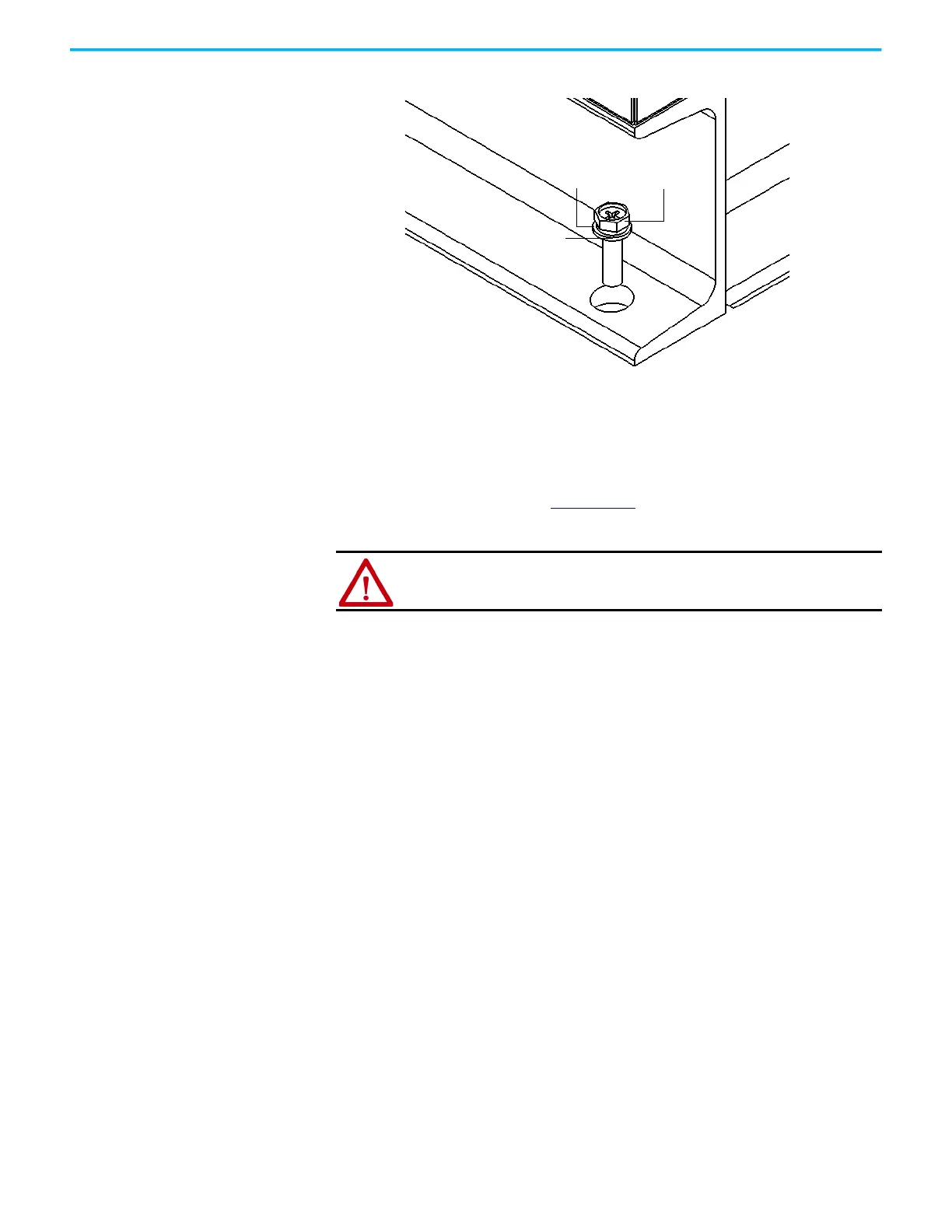
Figure 6 - Bolt Cabinet to Steel Base, B-Frame
Optional: The cabinet can also be welded to the steel base once it is securely
bolted, if desired.
Each weld location should be 100 mm (3.9 in.) for every 1000 mm (39.4 in.). See
Mounting Requirements in the PowerFlex 6000T Drives Shipping and
Handling Manual, publication 6000-PC100
) for further information on the
steel base and desired trench and mounting customer-specifications.
M16 bolt
Flat washer
Lock washer
ATTENTION: Failure to correctly anchor the cabinet may result in damage to
the equipment or injury to personnel.
 Loading...


