64 Rockwell Automation Publication 6000-IN100A-EN-P - August 2020
Appendix D Power Cabling and Control Signal Wiring Details
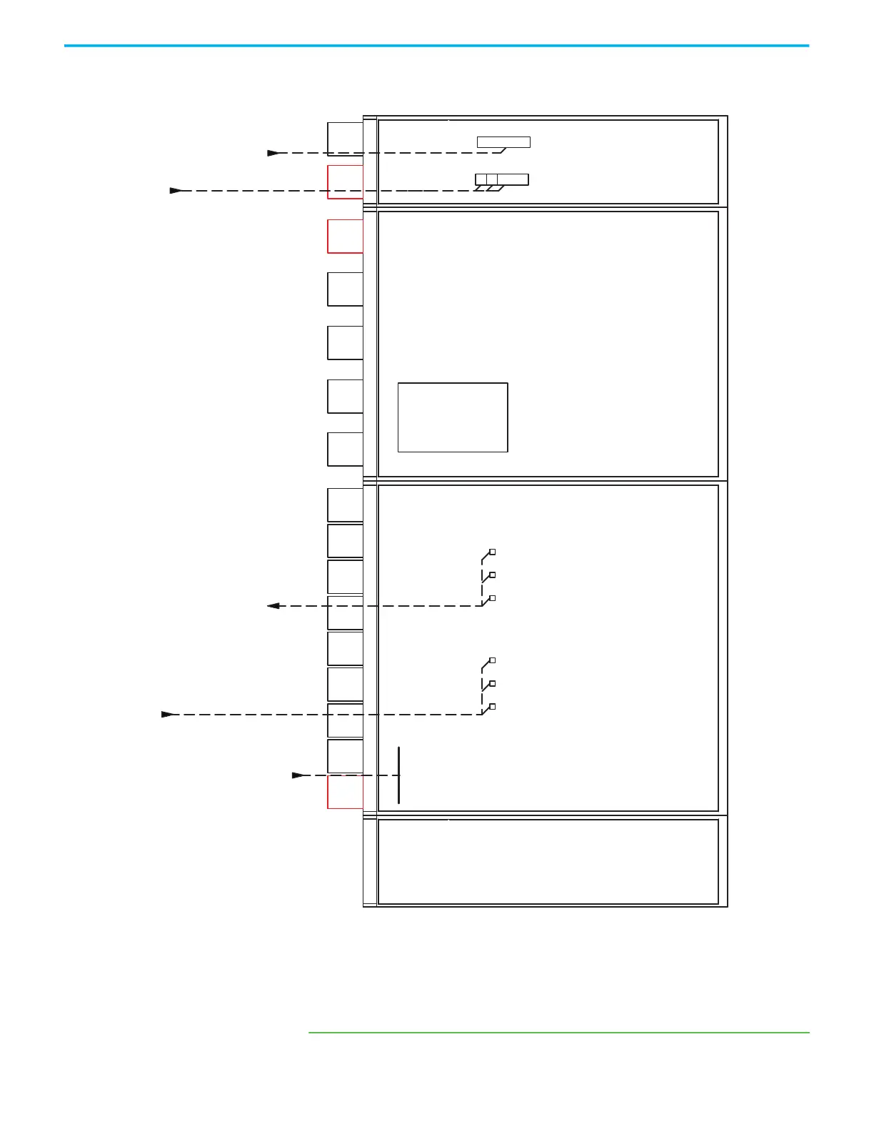
Figure 33 - Schematic Diagram of the Drive System without a Bypass Cabinet, B-Frame with one
Transformer
(a)
(a) Wiring locations are for design reference only; actual wiring must comply with the drawings
that are provided with the drive.
/// :98
9)'
9)'
/
1
$$$
3(*5'
$
Fan
29
Customer Supplied
Ground
13.8 kV, 3 phase, 60 Hz
Upstream Circuit Breaker
(Customer scope of supply)
To Motor
Control Signal
DANGER:
The medium voltage drive is one component in this system, which includes an input device that is supplied by others.
The supplier of the input device is responsible for confirming that there is safe access to the input/output drive (if used) and safe access to the drive.
110/120/220/230/240V AC, 1 phase, 50/60 Hz.
Control Signal with Branch Circuit Protection
(Minimum 3 kVA Capacity is needed)
Fan
28
Fan
27
Fan
26
Fan
25
Fan
24
Fan
23
Fan
22
Fan
21
Fan
35
Fan
34
Fan
33
Fan
32
Fan
31
(1)
Fan
72
(1)
Fan
71
(1) Redundant fan number shown in red box
Fan
Control
Cabinet
T1
Filter Cabinet /
Junction Cabinet
Transformer Cabinet 1Power Cell CabinetControl Cabinet
 Loading...


