7 Rockwell Automation Publication 1783-IN022A-EN-P - July 2023
Stratix 5200 Ethernet Managed Switches Installation Instructions
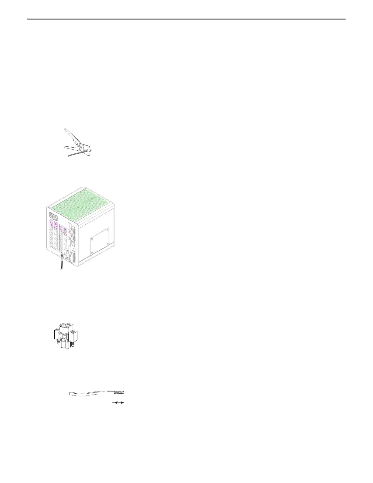
Ground the Switch
For DC power connections, use UL- and CSA-rated, style 1007 or 1569 twisted-pair copper appliance wiring material (AWM) wire. Use at least 4 mm
2
(12 AWG) wire to connect to the
external grounding screw.
The ground lug is not supplied with the switch. You can use one of these options:
• Single ring terminal
• Two single ring terminals
To ground the switch to earth ground, follow these steps. Be sure to follow any grounding requirements at your site.
1. To remove the ground screw from the front panel of the switch, use a Phillips screwdriver or a ratcheting torque screwdriver with a Phillips head.
Store the ground screw for later use.
2. Use the guidelines from the manufacturer to determine the wire length to be stripped.
3. Insert the ground wire into the ring terminal lug and use a crimping tool to crimp the terminal to the wire.
If you are using two ring terminals, repeat this action for the second ring terminal.
4. Slide the ground screw through the terminal.
5. Insert the ground screw into the functional ground screw opening on the front panel.
6. Use a ratcheting torque screwdriver to tighten the ground screws and ring terminal lugs to the switch front panel to 0.4 N
m (3.5 inlb).
Do not exceed the recommended torque.
7. Attach the other end of the ground wire to a grounded bare metal surface, such as a ground bus, a grounded DIN rail, or a grounded bare rack.
Wire the DC Power Source
To wire the DC power source for the switch, follow these steps.
1. Locate the power connector.
2. Identify the positive and return DC power connections.
The positive DC power connection is labeled PWR A, and the negative DC power connection is the adjacent connection labeled PWR B.
3. Measure a length of 0.82…0.52 mm
2
(18…20 AWG) copper wire long enough to connect to the DC power source.
4. Use an 18-gauge wire-stripping tool to strip each of the two wires to 6.3 mm (0.25 in.) ± 0.5 mm (0.02 in.).
Do not strip more than 6.8 mm (0.27 in.) of insulation from the wire. Stripping more than the recommended amount of wire can leave wire exposed after installation.
6.3 mm (0.25 in.) ± 0.5 mm (0.02 in.)
 Loading...


