9 Rockwell Automation Publication 1783-IN022A-EN-P - July 2023
Stratix 5200 Ethernet Managed Switches Installation Instructions
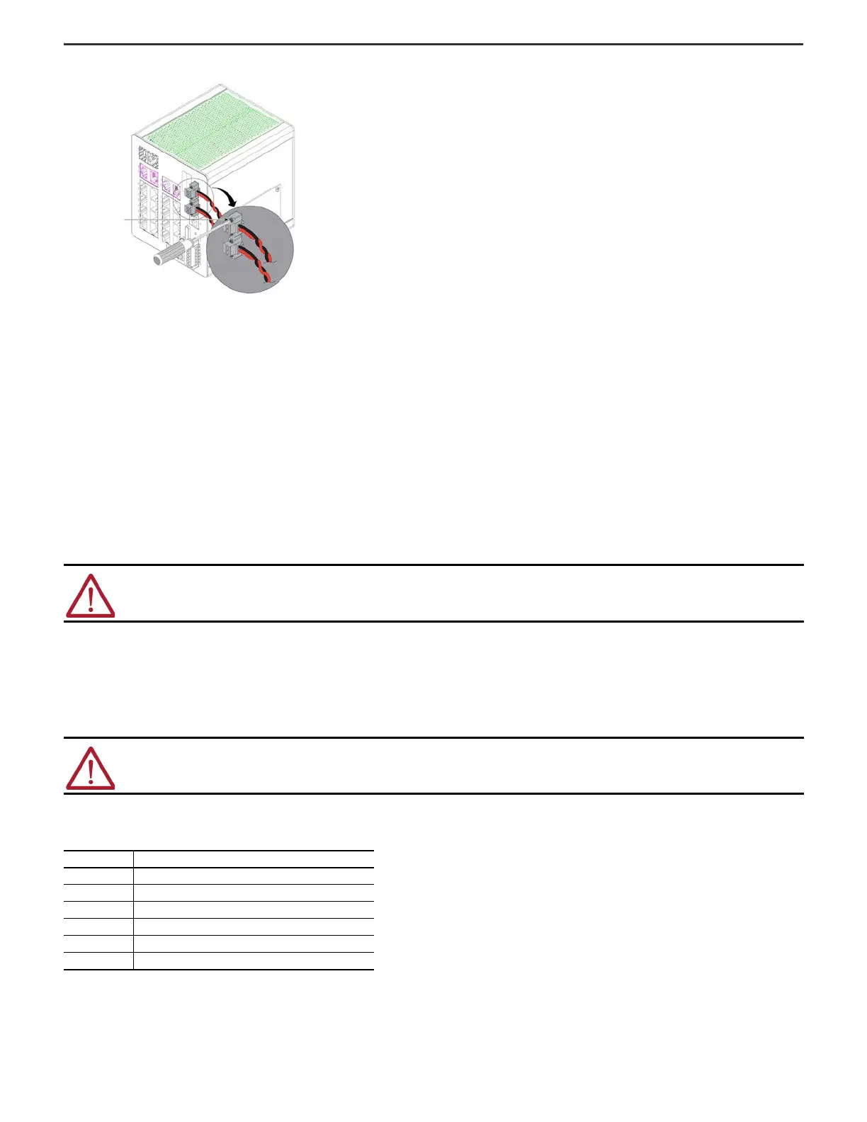
2. Use a ratcheting torque flathead screwdriver to tighten the captive screws on the sides of the power connectors.
When you test the switch, one power source is sufficient. If you install a second power source, repeat this procedure for the second power connector (Pwr B).
3. When you install the switch, secure the wires from the power connectors to the rack by using tie wraps.
Wire External Alarms
The switch has two alarm inputs and one Form C (single-pole, double-throw) alarm output relay circuits for external alarms. The input alarm relay circuits are designed to sense if
the alarm input is open or closed relative to the alarm input reference pin. The output alarm relay circuit has one Form C relay, with one normally open (N.O.) and one normally
closed (N.C.) contact. You can configure the output alarm relay as either normally energized or normally de-energized by using the CLI.
Alarm signals are connected to the switch through the 6-way alarm relay connector. Three connections are dedicated to the two alarm input circuits:
• Alarm input 1 (IN1)
• Alarm input 2 (IN2)
• Isolated reference ground
An alarm input and the reference ground wiring connection are required to complete one input alarm circuit. You must provide either an N.O. or an N.C. dry contact to complete the
alarm circuit between reference ground and IN1 or IN2.
The three remaining connections for the Form C output alarm circuit are as follows:
• N.O. output
• N.C. output
•common
An alarm output and the common wiring connection are required to complete one output alarm circuit. The Form C output alarm relay provides one N.O. and one N.C. dry contact.
The labels for the alarm relay connector are on the switch panel.
ATTENTION: Do not apply an external voltage source to either the IN1 or IN2 alarm inputs. Limit alarm output wiring to 60V DC, 0.5 A.
ATTENTION: Wire connections to the power and relay connector, must be UL- and CSA-rated, style 1007 or 1569 twisted-pair copper appliance wiring
material (AWM) wire.
Alarm Relay Connector Labels
Label Connection
N.O. Alarm Output Normally Open (N.O.) connection
COM Alarm Output Common connection
N.C. Alarm Output Normally Closed (N.C.) connection
IN2 Alarm Input 2
REF Alarm Input Reference Ground connection
IN1 Alarm Input 1
 Loading...


