ITA ENG FRA ESP DEU POR
6-1622349 rev.3 28/03/2019 pag. 1
ACTION CONTROL UNIT for Tecno-cat
INSTRUCTIONS FOR INSTALLATION
1. Introduction
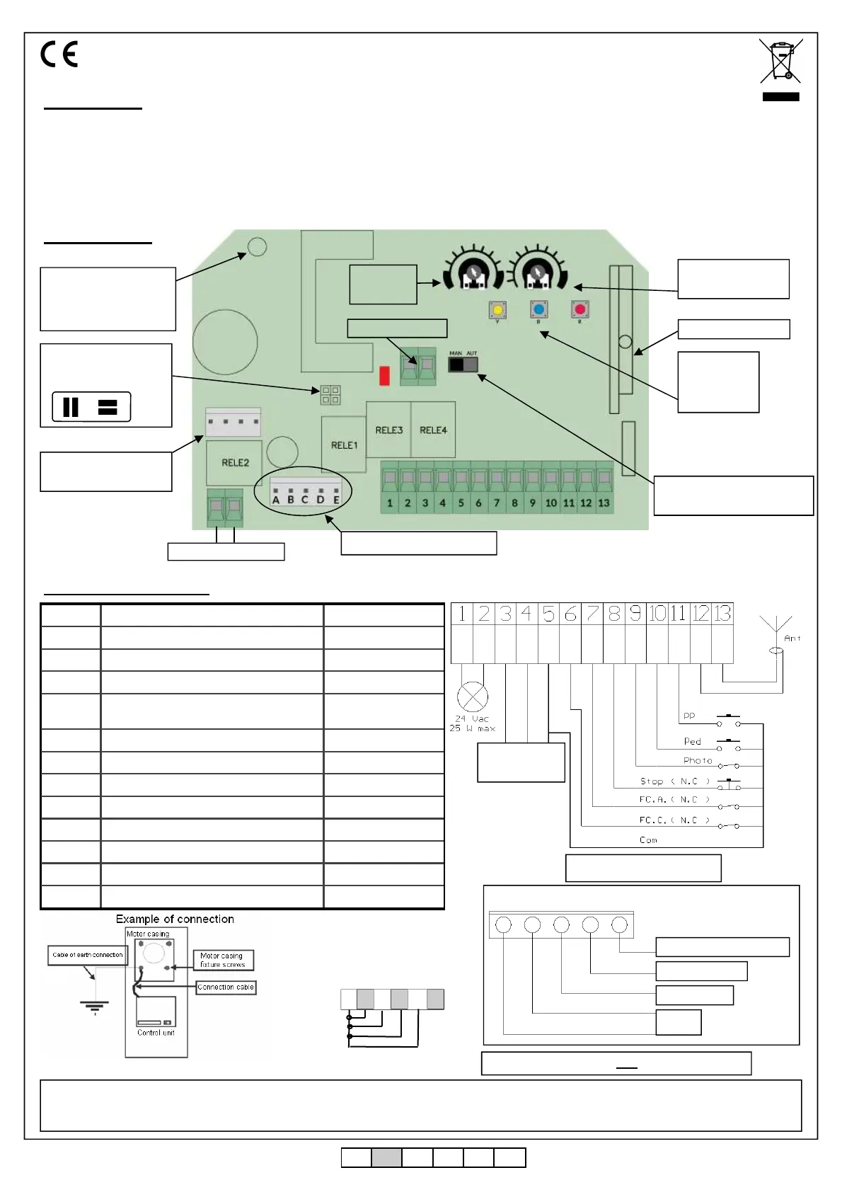
Any contact which is
Normally Closed (N.C.)
Must be bridged to the
common if not used.
5 6 7 8 9 10
3. Electrical connections
IMPORTANT: to obtain a correct working of the accessories (photo devices in particular) connected to the control box, it is very important that the
entire system (motor+ control box) has a single mass reference system. You must therefore connect a small cable between the motor casing and the
control box at the point shown in the figure. If there is a good ground connection it is advisable to connect it to the system.
Photocells
Power supply
Motor/ Encoder Connector.
A B C D E
Motor
Encoder +5Vcc (brown)
Signal (green)
GND (white)
Note: Cable colours valid only for Tecno-cat motor.
Action is a control unit dedicated to the movement of the chain barrier with 24Vdc motor. The coexistance of various types of safeties such as the con-
trol of the absorbed power by the motor and the velocity of the motor allows a rapid intervention of the anti – squeezing security (sense). Through the
encoder present in the motor it is possible to control the exact position of the chain and to use it without mechanical limit switches. The control unit has
inputs for mechanical limit switches, for the step by step button, for the pedestrian opening, for the safety photocells and the output for flashing light 24
Vac. The unit also allows the regulation by trimmer both the automatic re-closure and the motor force. Action can control motors at 24 – 30 Vcc with a
maximum consumption of 7A.
Terminal Function Setting
1 – 2 Flashing signal output
OUT: 24 Vac 25 W MAX
3 Positive power supply TX & RX photocell
OUT: +24Vcc
4 Negative power supply TX photocell
OUT: GND TX
5 Negative power supply RX photocell and
common button and safety
OUT: GND RX
Common
6 Stop closure button input
Normally closed (NC)
7 Stop open button input
Normally closed (NC)
8 STOP button input
Normally closed (NC)
9 RX photocell contact input
Normally closed (NC)
10 Pedestrian button input
Normally open (NO)
11 Relay button input
Normally open (NO)
12 Antenna screen input
GND
13 Antenna input
Antenna
2. Configuration
Radio connector
Setting maximum
torque threshold.
Manual selector (Left) /
automatic (Right).
Automatic
re-closure
Motor/ Encoder Connector
Buttons:
1 = yellow
2 = Blue
3 = Red
Jumper ( if present)
in order to invert the
motor phases
Use this point to connect
the motor’s casing to the
control panel and to the
ground.
Connector for the
battery charger.
24Vac Power supply
Courtesy light