NetWay8/NetWay16 - 3 -
Note: All cabling and wire must be UL Listed and/or Recognized wire suitable for their application.
6. Connect structured cables from port marked [OUT] on NetWay to PoE compliant camera/edge
devices (Fig. 1a, pg. 3, Fig. 5, pg. 5).
Note: For UL294 applications, the products are to be tested as part of a complete Access Control System and in
accordance with UL Listed Access Control Devices.
Note: All interconnected devices must be UL Listed.
7. Upon completion of wiring set illuminated master power disconnect circuit breaker to the RESET (ON)
position (Fig. 1d, pg. 3).
8. Port status LEDs on the NetWay will initialize when PoE devices are connected as follows:
- LED will illuminate when devices are IEEE 802.3af compliant.
- LED will blink once and illuminate when devices are IEEE 802.3at compliant (PoE+).
Port Status and LED Flash Codes:
Port Status Flash Codes Description
All Ports Off Sequential LED Port Scan No devices connected
Port Off OFF LED OFF
Port On ON LED ON
Class 4 detection Port Blinks 2 times Enables power to PoE devices.
Non-compliant Device 2Hz Will prevent port from turning on.
Port Overload Fault 5Hz Will prevent port from turning on.
4 Port Overload Grouped 5Hz
4 LEDs
Will prevent ports from turning on.
8 Port Overload Grouped 5Hz
LED’s 1-8 Power Supply Overload for ports 1-8.
LED’s 9-16 Power Supply Overload for ports 9-16.
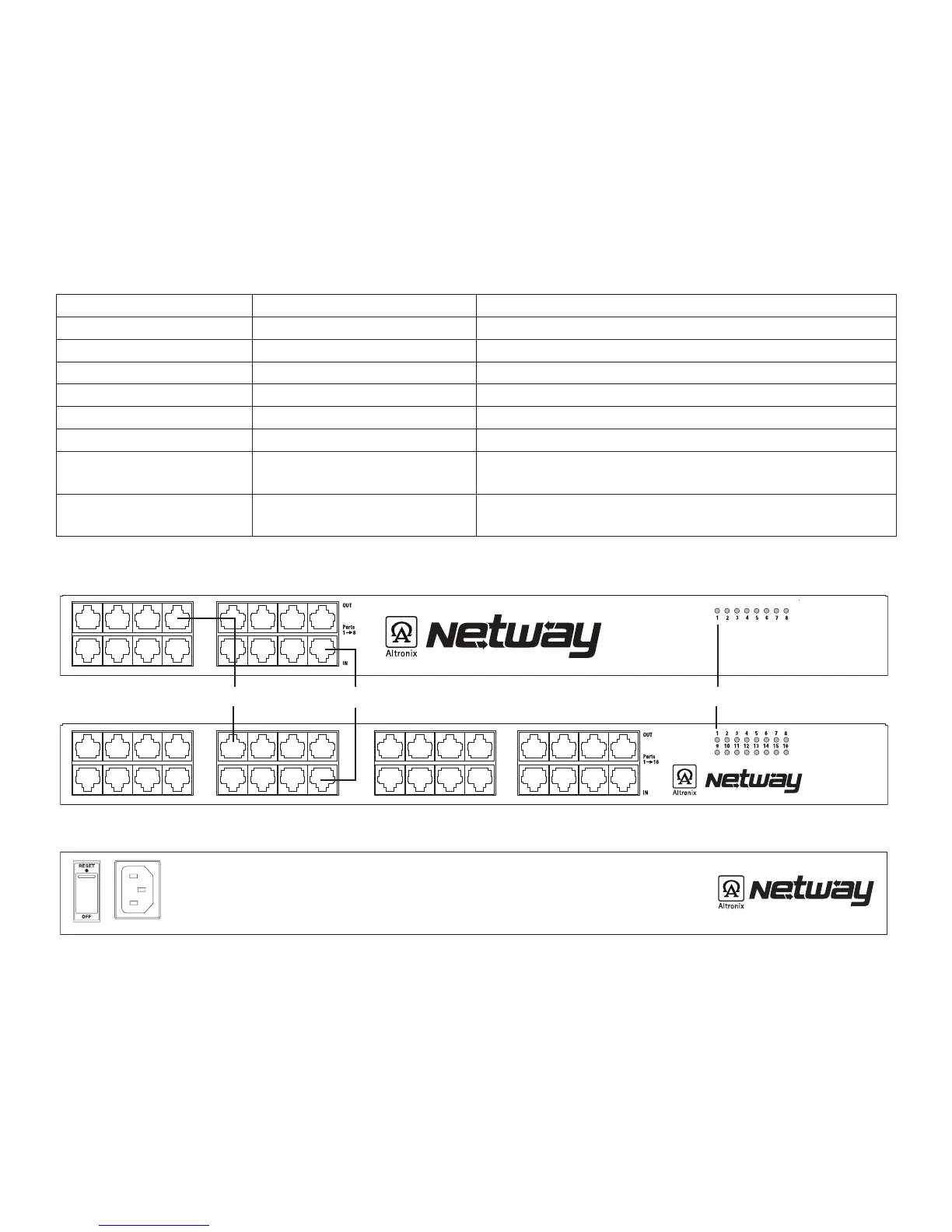
Fig. 1
1a OUT 1-8 (NetWay8), OUT 1-16 (NetWay16): Structured cable to PoE compliant cameras/edge devices.
1b IN 1-8 (NetWay8), IN 1-16 (NetWay16): Structured cable to ethernet switch or video server.
1c LED(s) 1-8 (NetWay8), 1-16 (NetWay16): Port status LEDs.
1d Illuminated master power disconnect circuit breaker (switch):
• OFF position Circuit breaker tripped Switch not illuminated.
• RESET (ON) position Switch illuminated.
1e IEC 320 Connector: 115VAC 60Hz (grounded line cord included).
AC POWER
NetWay8 & NetWay16 - Rear Panel
NetWay16 - Front Panel
1a 1c1b
1d
1e
 Loading...