2 1X-F Series Quick Installation Guide
Fire routing outputs
EN 54-2 OUT4
EN 54-2 Scandinavia OUT4
NEN 2535 OUT3 (automatic)
OUT4 (manual)
Mains fuses and batteries
Mains fuses
110 VAC [1] T 3.15A 250V
240 VAC T 2A 250V
[1] See your installation manual for 110 VAC operation requirements.
Batteries
Two- and four-zone panels 12 V, 7.2 Ah
Eight-zone panel 12 V, 7.2 Ah or 12 V, 12 Ah
Basic configuration
Default configuration
Operating mode 01 (EN 54-2)
Zone end-of-line Passive
Zone type Mixed
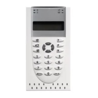
The configuration controls are located on the control
panel interface.
Configuration controls
Button Function
1 Scroll to the next configuration menu on the seven-
segment display.
2 Scroll to the next configuration value for the active menu
on the seven-segment display.
3 Scroll to the previous configuration menu on the seven-
segment display.
4 Scroll to the previous configuration value for the active
menu on the seven-segment display.
Enter Confirm a menu selection or a value selection entry.
The configuration controls are also used to enter the
user level password. The seven-segment display is
visible when the control panel cover is removed.
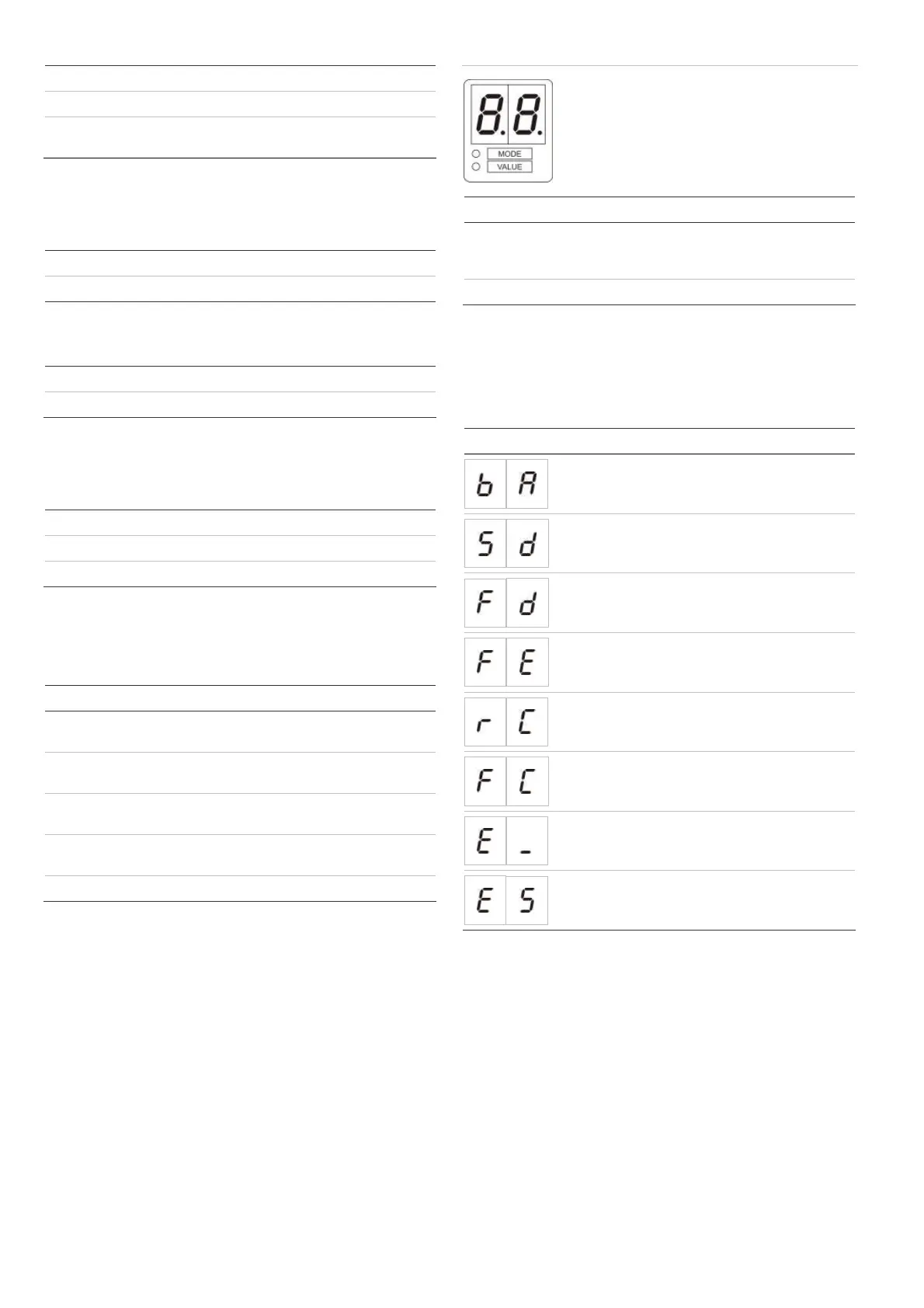
Seven-segment display
LED Indications
Mode Steady: Select a menu using buttons 1 and 3.
— or —
Flashing: Select a submenu using buttons 1 and 3.
Value Steady: Select a value using buttons 2 and 4.
Basic configuration menu
Selected options from the basic configuration menu are
shown below. The default password for basic
configuration is 3333.
Display Menu Values
Basic default
configuration
01 to 32
Sounder delay 00 to 10 minutes
Fire routing delay 00 to 10 minutes
Extended fire routing
delay
00 to 10 minutes
Restore previous
configuration
Restore factory
configuration
Exit without saving
Exit and save
 Loading...