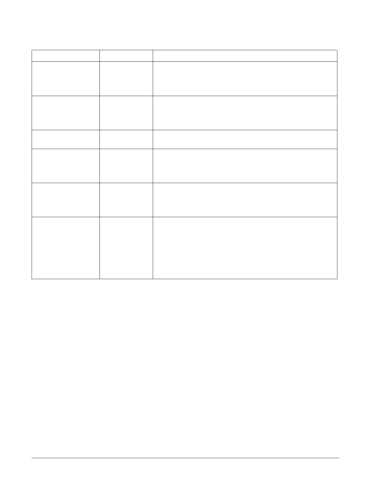
Table 3-2 Audio I
2
S memory map (continued)
Address Name Description
0x40024010
TXBUF Transmit Buffer FIFO Data Register. This is a write-only register.
[31:16] Left channel
[15:0] Right channel
0x40024014
RXBUF Receive Buffer FIFO Data Register. This is a read-only register.
[31:16] Left channel
[15:0] Right channel
0x40024018 -
0x400242FC
RESERVED -
0x40024300
ITCR Integration Test Control Register
[31:1] Reserved
[0] ITCR
0x40024304
ITIP1 Integration Test Input Register 1
[31:1] Reserved
[0] SDIN
0x40024308
ITOP1 Integration Test Output Register 1
[31:4] Reserved
[3] IRQOUT
[2] LRCK
[1] SCLK
[0] SDOUT
3 FPGA platform overview
3.14 Audio I
2
S
ARM 100896_0000_00_en Copyright © 2017 ARM Limited or its affiliates. All rights reserved. 3-39
Non-Confidential

 Loading...