1-18
Chapter 1: Product introduction
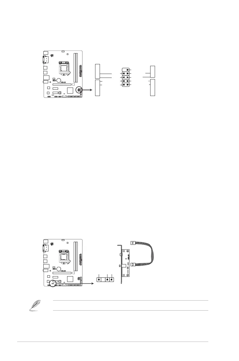
The S/PDIF module is purchased separately.
10. Digital audio connector (4-1 pin SPDIF_OUT)
ThisconnectorisforanadditionalSony/PhilipsDigitalInterface(S/PDIF)port.Connect
theS/PDIFOutmodulecabletothisconnector,theninstallthemoduletoaslot
opening at the back of the system chassis.
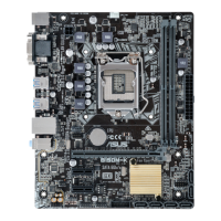
9. System panel connector (10-1 pin F_PANEL)
Thisconnectorsupportsseveralchassis-mountedfunctions.
• SystempowerLED(2-pinPWRLED)
This2-pinconnectorisforthesystempowerLED.ConnectthechassispowerLED
cabletothisconnector.ThesystempowerLEDlightsupwhenyouturnonthesystem
power,andblinkswhenthesystemisinsleepmode.
•
Hard disk drive activity LED (2-pin +HDLED)
This2-pinconnectorisfortheHDDActivityLED.ConnecttheHDDActivityLEDcable
tothisconnector.TheHDLEDlightsuporasheswhendataisreadfromorwrittento
theHDD.
•
ATX power button/soft-off button (2-pin PWRBTN)
This connector is for the system power button.
•
Reset button (2-pin RESET)
This 2-pin connector is for the chassis-mounted reset button for system reboot without
turning off the system power.
PIN 1
PWR BTN
GND
PWR
PWR_LED-
PWR_LED+
(NC)
HWRST#
Ground
HDD_LED-
HDD_LED+
F_PANEL
+PWR LED
+HDD_LED RESET
B150M-K D3
B150M-K D3 System panel connector
B150M-K D3
B150M-K D3 Digital audio connector
SPDIF_OUT
+5V
SPDIFOUT
GND
 Loading...