1-11Chapter 1: Product introduction
6. USB 2.0 ports 1 and 2. These two 4-pin Universal Serial Bus (USB) ports are for USB
2.0/1.1 devices.
7. USB 2.0 ports 3 and 4. These two 4-pin Universal Serial Bus (USB) ports are for USB
2.0/1.1 devices.
8. DVI-D port. This port is for any DVI-D compatible device. DVI-D can’t be converted to
output RGB Signal to CRT and isn’t compatible with DVI-I.
9. Video Graphics Adapter (VGA) port. This 15-pin port is for a VGA monitor or other
VGA-compatible devices.
10. USB 2.0 ports 5 and 6. These two 4-pin Universal Serial Bus (USB) ports are for USB
2.0/1.1 devices.
1.7.2 Internal connectors
• For a fully congured system, we recommend that you use a power supply unit (PSU)
that complies with ATX 12 V Specication 2.0 (or later version) and provides a minimum
power of 350 W.
• DO NOT forget to connect the 4-pin ATX +12V power plug. Otherwise, the system will
not boot up.
• We recommend that you use a PSU with higher power output when conguring a
system with more power-consuming devices. The system may become unstable or may
not boot up if the power is inadequate.
•
If you are uncertain about the minimum power supply requirement for your system,
refer to the Recommended Power Supply Wattage Calculator at http://support.asus.
com/PowerSupplyCalculator/PSCalculator.aspx?SLanguage=en-us for details.
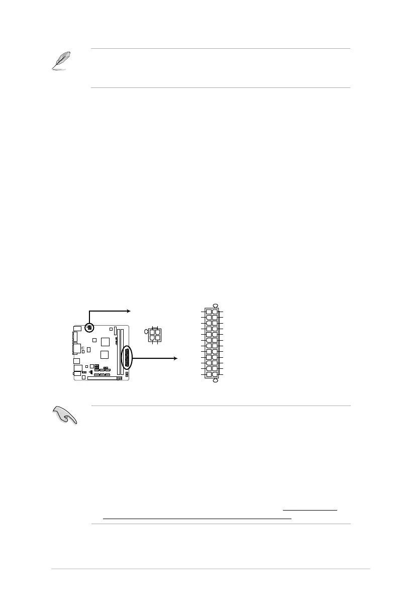
1. ATX power connectors (24-pin EATXPWR, 4-pin ATX12V)
These connectors are for ATX power supply plugs. The power supply plugs are
designed to t these connectors in only one orientation. Find the proper orientation and
push down rmly until the connectors completely t.
C60M1-I
C60M1-I ATX power connectors
EATXPWR
ATX12V
PIN 1
GND
+5 Volts
+5 Volts
+5 Volts
-5 Volts
GND
GND
GND
PSON#
GND
-12 Volts
+3 Volts
+3 Volts
+12 Volts
+12 Volts
+5V Standby
Power OK
GND
+5 Volts
GND
+5 Volts
GND
+3 Volts
+3 Volts
PIN 1
+12V DC
+12V DC
GND
GND
To congure an 8-channel audio output:
Use a chassis with HD audio module in the front panel to support an 8-channel audio
output.
 Loading...