1-3Chapter 1: Product introduction
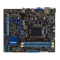
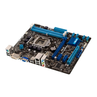
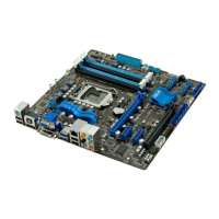
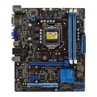
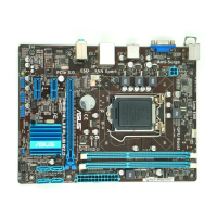
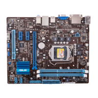
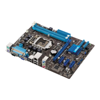
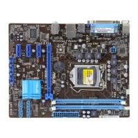
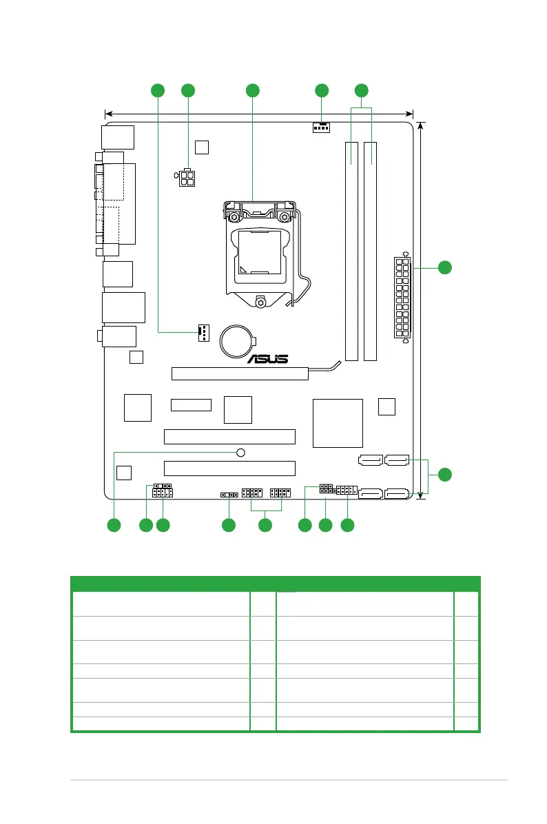
1.2.3 Motherboard layout
1.2.4 Layout contents
Connectors/Jumpers/Slots/LED Page Connectors/Jumpers/Slots/LED Page
1. CPU and chassis fan connectors
(4-pin CPU_FAN, 4-pin CHA_FAN)
1-19 8. Clear RTC RAM (3-pin CLRTC) 1-15
2. ATX power connectors (24-pin EATXPWR,
4-pin ATX12V)
1-18 9. USB connectors (10-1 pin USB78, USB910) 1-20
3. Intel
®
LGA1155 CPU socket 1-4 10. Chassis intrusion connector (4-1 pin
CHASSIS)
1-18
4. DDR3 DIMM slots 1-9 11. Front panel audio connector (10-1 pin AAFP) 1-17
5. Intel
®
H61 Serial ATA 3.0Gb/s connectors
(7-pin SATA3G_1/2/3/4)
1-20 12. Digital audio connector (4-1 pin SPDIF_OUT) 1-19
6. System panel connector (20-8 pin PANEL) 1-21 13. Standby power LED (SB_PWR) 1-1
7. Speaker connector (4-pin SPEAKER) 1-21
P8H61-M PLUS V3
PCI2
PCI1
PCIEX1_1
USB56 USB78
CLRTC
SPEAKER
CHASSIS
AAFP
ATX12V
EATXPWR
CPU_FAN
CHA_FAN
Lithium Cell
CMOS Power
Super
I/O
ALC
887-VD
RTL
8111E
EPU
64Mb
BIOS
ASM
1083
SB_PWR
SPDIF_OUT
24.4cm(9.6in)
LGA1155
Intel
®
H61
DDR3 DIMM_A1 (64bit, 240-pin module)
DDR3 DIMM_B1 (64bit, 240-pin module)
SATA3G_2SATA3G_4
SATA3G_1SATA3G_3
AUDIO
KBMS
LAN1_USB12
USB34
19.8cm(7.8in)
F_PANEL
PCIEX16
VGA
LPT
COM
21 43 1
5
2
7 69 8101113 12
 Loading...