Power Amplifiers
SPA2-150/200P
15
4.1 Description
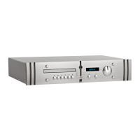
The SPA2-150 and SPA2-200P are high quality power amplifiers designed to partner
ATC passive monitors and other loudspeaker systems. They are both capable of
output power considerably in excess of specification. Both also incorporate the same
gain reduction and loudspeaker protection circuits as ATC’s active monitors. This
ensures that even when working at very high levels the amplifiers are held back from
clipping so improving the subjective performance and protecting the loudspeakers
from damage.
The SPA2-200P features a stereo pair of balanced inputs on XLR sockets while the
SPA2-150 incorporates switch selectable balanced and unbalanced signal inputs on
XLR and RCA phono sockets respectively. Loudspeaker output connections on both
power amplifiers are made through two pairs of WBT connectors.
The SPA2-200P includes a multi-pin connector on the rear panel that provides wired
remote control interface facilities while the SPA2-150 can be switched into and out of
Standby mode by either ATC remote handset.
Both power amplifiers incorporate comprehensive performance monitoring and
feedback through a front panel display.
4.2 Installation
The SPA2-200P and SPA2-150 are designed to be free standing. The power
dissipation of the amplifiers is considerable and makes them warm to touch.
Temperature stability will be reached after approximately three hours from mains
switch-on but full audio performance is available immediately and is not influenced
by temperatures within the amplifiers’ normal operating range. Care must be taken
not to obscure the ventilation holes in the top and bottom covers. Please contact
ATC for advice if the amplifier is required to be mounted in an enclosed area.
The SPA2-150 is an aesthetic match for the SCA2 preamplifier and it is quite in
order to sit the SCA2 on top of the SPA2-150.A general recommendation regarding
the layout of the system is that the distance between the power amplifier and
loudspeakers should be minimised. Reducing the length of speaker cables improves
the control of amplifier over the loudspeaker system through the reduced
resistance of the loudspeaker leads. It may therefore be appropriate to locate the
power amplifiers close to the loudspeakers.
There is no general benefit from reducing the length of the interconnect from the
an ATC preamplifier to the power amplifier, especially when balanced connections
are used. However, non ATC preamplifiers may not be capable of driving cables of
more than a few metres.
4.3 Mains Connection
The SPA2-150 and SPA2-200P can be used with mains voltages from 100V to 240V,
50/60Hz. Mains voltage is factory set and should only be adjusted by ATC or your
local dealer or distributor. It is wise to ensure that the local mains voltage matches
that specified on the rear panel before applying mains power.
The mains cable is specifically supplied to comply
with local statutory safety approvals and
alternatives should not be substituted. If you
intend to use your power amplifier in an
alternative territory please contact ATC for
advice. The mains connection must always be
earthed.
A power supply fuse is fitted to the rear panels of
the power amplifiers. The fuse is 20mm “Type T
anti-surge”. Should a unit fail to switch on when
the power switch is operated the fuse should be
inspected. Lift out the fuse holder cover using a
small flat-blade screwdriver, remove the fuse and
inspect it for damage. The fuse rating is 3.15A for
200V - 250V mains voltage and 6.3A for 100V -
120V. Fuses most often fail only because of a
serious electrical fault. If this is the case then
simply replacing the fuse will only result in another
fuse failure. The power amplifier should be
returned to ATC for service if a second fuse fails.
4.4 Inputs
The SPA2-150 is fitted with both unbalanced RCA
Phono and balanced XLR inputs. A switch on the
rear panel selects between the two. The SPA2-
200P incorporates only balanced XLR inputs.
Note: Do not attempt to connect both balanced
and unbalanced inputs at the same time. The
selector switch is not a toggle between the two
inputs. The XLR and RCA input connectors are
wired in parallel and the switch merely arranges
for either balanced or unbalanced input.
The signal is present on the centre conductor of
an unbalanced RCA Phono style input and the
signal return is made via the screened outer. If
there is any hum present on the inputs this must
be traced to its source and not suppressed by the
removal of screens or earths. Removal of the
screen on an unbalanced input is likely to result in
uncontrollably loud hum.
All signal cables and plugs should be of a good
quality. Poor cable and plug quality will
compromise the performance of your system.The
signal input pin configuration for XLR sockets is
illustrated in Diagram 1 while Diagram 2 illustrates
a balanced cable.
 Loading...