16
Power Amplifiers
SPA2-150/200P
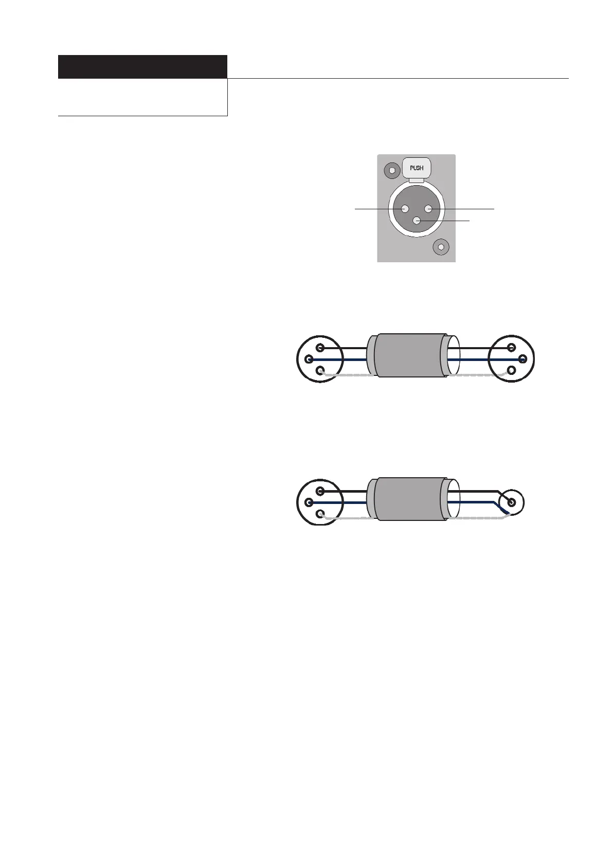
4.5 Signal Cable Options
Balanced cables are always the preferred option,
for the SPA2-150P however unbalanced
connection is possible. Diagrams 2 and 3 illustrate
the signal cable connections required for each
option. Balanced (XLR to XLR) connection offers
lower noise and better immunity to “hum” pick-
up. Unbalanced (XLR to Phono or Two Pole Jack)
connection carries risk of hum caused by multiple
signal earths.
Hum problems resulting from unbalanced
connection may be reduced by making ONE of the
following modifications to the signal cable
connections: If the driving preamplifier (or desk) is
“double insulated” (i.e. has no mains earth),
disconnect the signal cable screen at the RCA
Phono plug end. Alternatively, disconnect the signal
cable screen at the XLR end.This second option will
make the source the reference signal earth.
4.6 Outputs
Loudspeaker connections are made to the SPA2-
150 and SPA2-200P through WBT connectors on
the rear panels. The left and right channels are
clearly marked. The loudspeaker terminals are
labelled positive and negative. The wire used for
the connections to the monitors will have some
identification for the positive conductor. Usually
this is red, but may be a moulded stripe on the
insulation. The terminals will accept either bare
wire up to 5.7mm diameter or 4mm male plugs.
When bare wire connections are made the
insulation should be carefully removed to expose
12mm of conductor. The conductors should be
tightly twisted together and inserted into the
connector ensuring that no stray strands of wire
cause a short circuit.
It is important that both loudspeakers are
connected with the same polarity. That is; both
positive loudspeaker terminals are connected back
to positive amplifier terminals and both negative
loudspeaker terminals connected back to negative
amplifier terminals.
The SPA2-150 and SPA2-200P are suitable for
loudspeaker systems with a nominal impedance of
4 Ohms or greater.
Diagram 1 - input connection pins
Diagram 2 - balanced cable
Diagram 3 - unbalanced cable
Pin 1, ScreenPin 2, Signal (hot)
Two Core Screened Cable
Pin 3, Signal (return)
3 Pin Male XLR
Connector
3 Pin Female XLR
Connector
To Power Amplifier
Input
Hot
Return
Screen
To Source Output
1
2
3
1
2
3
Two Core Screened Cable
3 Pin Male XLR
Connector
Phono (RCA)
Connector
To Power Amplifier
Input
Hot
Return
Screen
To Source Output
1
2
3
4.7 Operation
Once connected to mains power and powered-up from the rear panel mains switch,
the front panel Standby button (or ATC remote handset Standby button) will switch
the SPA2-150 between standby and active modes. The SPA2-200P can only be
operated remotely by a custom wired remote system
With the power switch on, the front panel Standby indicator will illuminate. The unit
will then respond to control either from the front panel or, in the case of the SPA2-150
an ATC remote handset.The Standby button on the front panel will switch the amplifier
between active and standby modes. The rear panel power switch should be used to
isolate the SPA2-150 and SPA2-200P from the mains supply if the units are to be unused
for any significant period.
When switched into active mode the unit will go into an initialisation sequence under
the control of the internal microprocessor.The standby indicator will extinguish and
be replaced by the LED display displaying
0 followed by a flashing decimal point. At
this time it is quite possible that the loudspeakers will emit a mild thump as the
Installation cont’d
 Loading...