EasyManua.ls Logo

Atlas Copco Elektronikon Mk5 User Manual

Atlas Copco Elektronikon Mk5
24 pages
To Next Page IconTo Next Page
To Previous Page IconTo Previous Page
Page #21 background imageLoading...
Page #21 background image
13/08/2013 PM 9845 0187 01 Page 21 of 24
12. Profibus Protocol Implementation
12.1. Protocol Specification
The protocol is based on the standard Profibus-DP V0 protocol, with the following basic specifications:
Mode : RS485
Baudrate : 9.6k, 19.2k, 45.45k, 93.75k, 187.5k, 500k, 1.5M, 3M, 6M, 12M
Autobaud : Supported
Freeze Mode : Not Supported
Sync Mode : Not Supported
Slave Node Address Change : Not Supported
Diagnostics : Not Supported
No PTO or PNO certification available (Not mandatory for Profibus DP)
12.2. Master-slave concept
The profile is based upon the master-slave principle. This means that all communication is initiated by the master and a
reply is generated by the slave.
All buffers should be full length consistent.
12.3. Buffer structure
The profile can be used for buffers with differs length: 8, 16, 32 and 64 bytes. This buffer is split into 2 parts:
Header (B0) : 1 byte
data section : n * data record (7bytes)
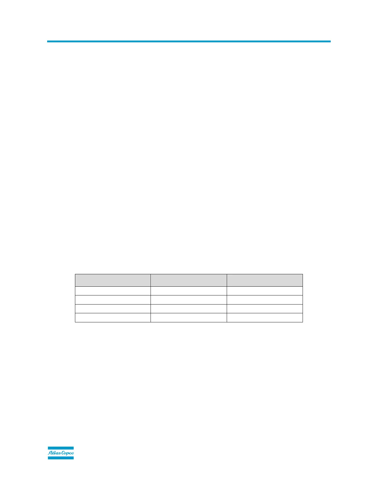
The buffer length is thus defined as follows:
Number of data records (n) Total buffer length Total used buffer length
1 8 8
2 16 15
4 32 29
8 64 57
NOTE: Not all functions allow more than 1 data record to be transferred. Basically read operations can be handled for several data records
in 1 cycle, while write operations are only valid for a single data record at a time.
12.2.1. Header
The header is a bit encoded 1 byte value. The interpretation is different for Master > Slave and Slave > Master
communication.
Master > Slave
The header is split into 3 areas:

Other manuals for Atlas Copco Elektronikon Mk5

Question and Answer IconNeed help?

Do you have a question about the Atlas Copco Elektronikon Mk5 and is the answer not in the manual?

Atlas Copco Elektronikon Mk5 Specifications

General IconGeneral
BrandAtlas Copco
ModelElektronikon Mk5
CategoryGateway
LanguageEnglish

Summary

1. General Information

2. Document Overview

3. Safety first

4. Copyright Notice

5. Document Information and History

6. Safety Precautions

6.1. Safety icons

Explains standard safety symbols used in the manual for warnings and notes.

6.2. Safety precautions during installation

Outlines critical safety measures and precautions to be followed during equipment installation.

6.3. Safety precautions during operation

Details essential safety guidelines for operating the equipment safely and correctly.

6.4. Safety precautions during maintenance or repair

Provides safety instructions and procedures for performing maintenance and repair tasks.

7. Preface

8. Physical Set-up

8.1. Modbus and/or Profibus in the network

Describes the physical setup for connecting Modbus and Profibus to the controller network.

8.2. Gateway module

Details the Gateway module, its purpose, and the connections required for its operation.

8.3. Gateway module

Specifies the pin-layout of the 9-pin Sub-D connector for the Gateway module.

9. Software installation and configuration

9.1. Display menu folder structure

Illustrates the hierarchical structure of the module's display menu and navigation.

9.1.1. Mainscreen folder [ ]

Describes the Mainscreen folder, its function, and behavior within the module's interface.

9.1.2. General Settings folder [GE]

Explains the General Settings folder and its subfolders for configuring module parameters.

10. Gateway Display Description

10.1. Icons

Explains the meaning and interpretation of various icons displayed on the Gateway module.

10.2. Leds

Describes the function and status indicated by the LEDs on the Gateway module.

10.3. Keyboard

Details the functions of the keyboard keys for navigating and interacting with the module.

10.4. Passwords / Access Codes

Provides information on entering customer passwords and access codes for system security.

11. Modbus Protocol Implementation

11.1. Supported Modbus specification

Lists the supported specifications and parameters for the Modbus protocol variant.

11.2. Supported Modbus functions

Details the Modbus message types and functions supported by the Elektronikon Mk5 controllers.

11.3. Function code - data field

Explains the Modbus function code and data field conventions in responses and exceptions.

11.4. Exception codes

Lists and explains various exception codes returned by the Modbus protocol.

11.5. Examples

Provides practical examples of Modbus communication sequences.

11.5.1. Illegal Data Address

Illustrates a Modbus request and answer for an illegal data address scenario.

11.5.2. Outlet Pressure and Outlet Pressure Status

Shows example Modbus requests and answers for outlet pressure and status.

11.5.3. Change the active pressure band

Demonstrates Modbus communication to change the active pressure band setting.

11.5.4. Start the machine

Provides an example of Modbus commands to start the machine.

12. Profibus Protocol Implementation

12.1. Protocol Specification

Outlines the basic specifications for the Profibus-DP V0 protocol implementation.

12.2. Master-slave concept

Explains the master-slave principle governing Profibus communication.

12.3. Buffer structure

Describes the structure and length of buffers used in Profibus data transfer.

12.4. Exception codes

Lists and explains exception codes specific to the Profibus protocol.

12.5. Examples

Provides practical examples of Profibus communication sequences.