2920 1390 02
4
Instruction book
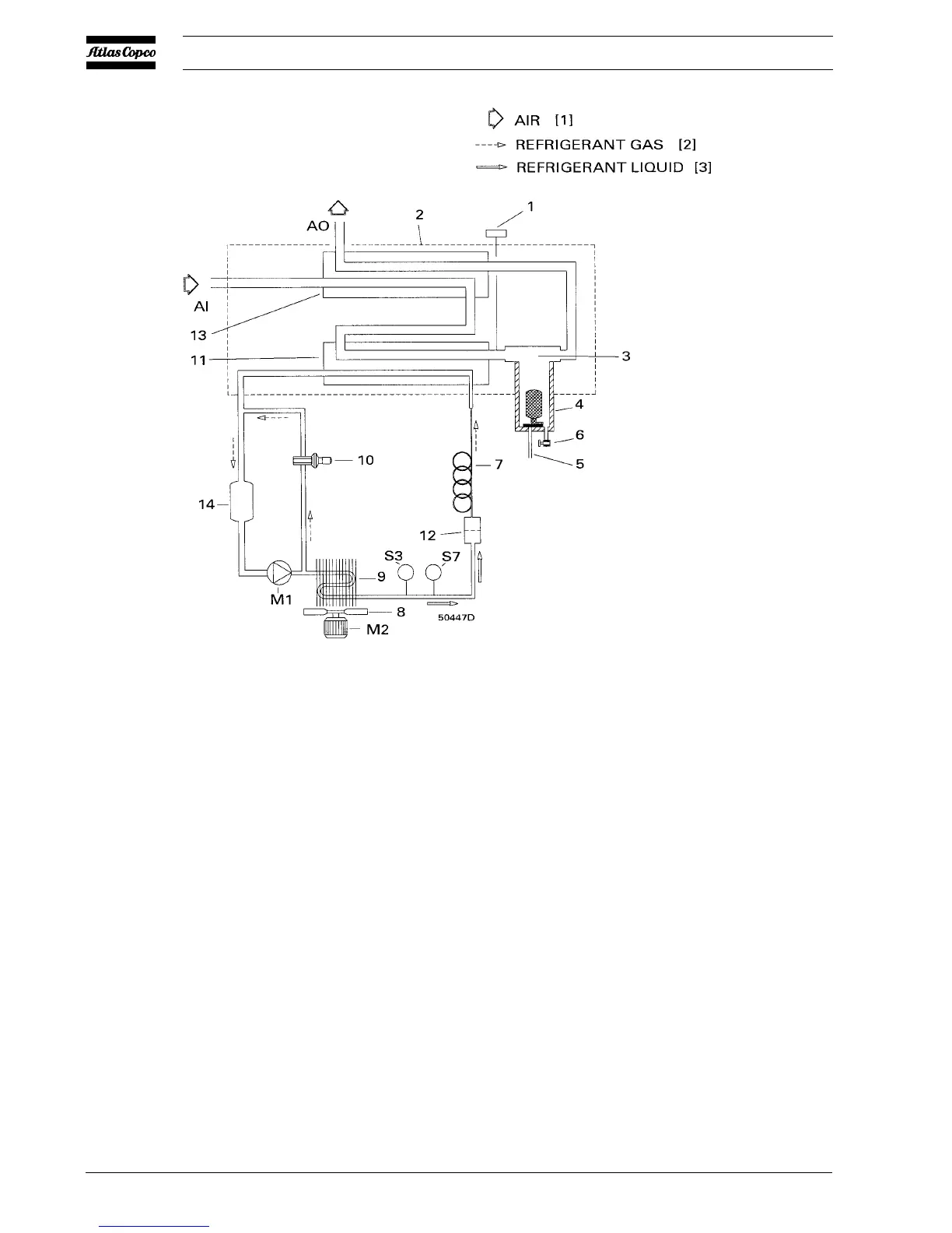
AI. Wet air inlet
AO. Dry air outlet
M1. Refrigerant compressor
M2. Condenser fan motor
S3. Fan control switch
S7. High pressure shut down switch
1. Pressure dewpoint gauge
2. Insulating block
3. Condensate separator
4. Condensate trap
5. Automatic condensate drain hose
6. Manual condensate drain valve
7. Capillary tube
8. Condenser cooling fan
9. Refrigerant condenser
10. Hot gas by-pass valve
11. Air/refrigerant heat exchanger/
evaporator
12. Liquid refrigerant dryer/filter
13. Air/air heat exchanger
14. Accumulator
Fig. 1.2 Air and refrigerant flow diagram
1.4 Automatic regulation system (Fig. 1.2)
The condenser pressure must be kept as constant as possible
to obtain stable operation, therefore, fan control switch (S3)
stops and starts the cooling fan.
When, at partial or no load, the evaporator pressure drops to
2.25 bar(e), the by-pass regulator opens and hot, high pressure
gas is fed to the evaporator circuit to prevent the evaporator
pressure from dropping any further.
1.5 Electrical system (Figs. 1.3 up to 1.6)
FD170 60Hz and FD230 60Hz dryers are 3-phase units, all other
FD dryers are single-phase units.
The refrigerant compressors (M1) of FD170 and FD230 dryers
are equipped with a crankcase heater (Rs). When voltage is
supplied, the heater is energized. It keeps the oil in the crankcase
warm to prevent condensing of refrigerant in the compressor
housing, which could result in serious damage of the compressor
at start (liquid knock).
 Loading...