2920 1390 02
12
Instruction book
2.3 Installation instructions
1. Install the dryer where the ambient air is as clean as possible
and where the temperature of the air will never exceed the
limits (see section 7). Keep the ventilation gratings of the
dryer free.
If necessary, take action to avoid external influences (wind,
draughts, etc.) through the ventilation gratings of the dryer,
as they may disturb the cooling air flow.
2. Connect the compressed air lines to the marked inlet and
outlet pipes of the dryer (Figs. 2.1 and 2.2). Provide an air
inlet valve and outlet valve. If a by-pass pipe and valve are
installed, the dryer can be serviced while by-passing the
dryer.
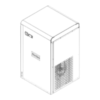
3. Fit manual condensate drain valve (2-Fig. 2.5).
Lay out the condensate drain hoses via a funnel towards a
drain collector to allow visual inspection. The hoses must
slope downwards. For draining of pure condensate, install
an oil/water separator; consult Atlas Copco.
If the condensate drain has been led down outside the
compressor room where it may be exposed to freezing
temperatures, it must be insulated.
4. A sticker dealing in short with the operating instructions
and explaining the pictographs is delivered with the
literature set. Affix the sticker next to the control panel.
Make yourself familiar with the instructions and pictographs
explained.
5. On single-phase dryers: Fit the electric plug to the voltage
supply cable. Plug in the dryer.
On 3-phase dryers: Check that the primary side
connections of transformer (T1-Figs. 1.5 and 1.6)
correspond with the supply voltage.
Check that the electrical installation corresponds to the local
codes. The dryer must be earthed and protected against
short circuits by fuses of the inert type in all phases. An
isolating switch must be installed near the dryer.
1. Pictograph, manual condensate drain
2. Manual condensate drain valve
3. Pictograph, automatic condensate drain
4. Automatic condensate drain
Fig. 2.5 Rear view
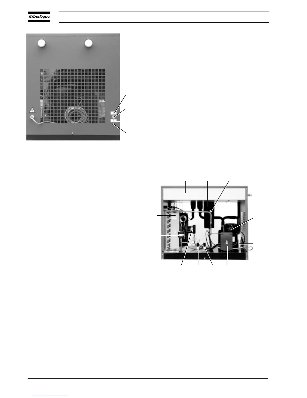
C3. Run capacitor
M1. Refrigerant compressor
M2. Condenser fan motor
S3. Fan control switch
S7. High pressure shut down switch
1. Hot gas by-pass valve
2. Condenser
3. Condensate trap
4. Insulating block with heat exchangers
5. Liquid refrigerant dryer/filter
6. Cubicle
Fig. 2.6 Side view
1
2
3
4
51534F
431
M1
C3
6S3S7M2
5
2
51541F
 Loading...