Instruction book
5.6 Adjustment of pilot valve on Trolley (Fig. 5.9)
The adjustment of the maximum or unloading pressure of the compressor is effected by means of pilot
valve (RV-Fig. 1.16). The valve also controls the difference between the preset maximum pressure and
that at which compression is resumed.
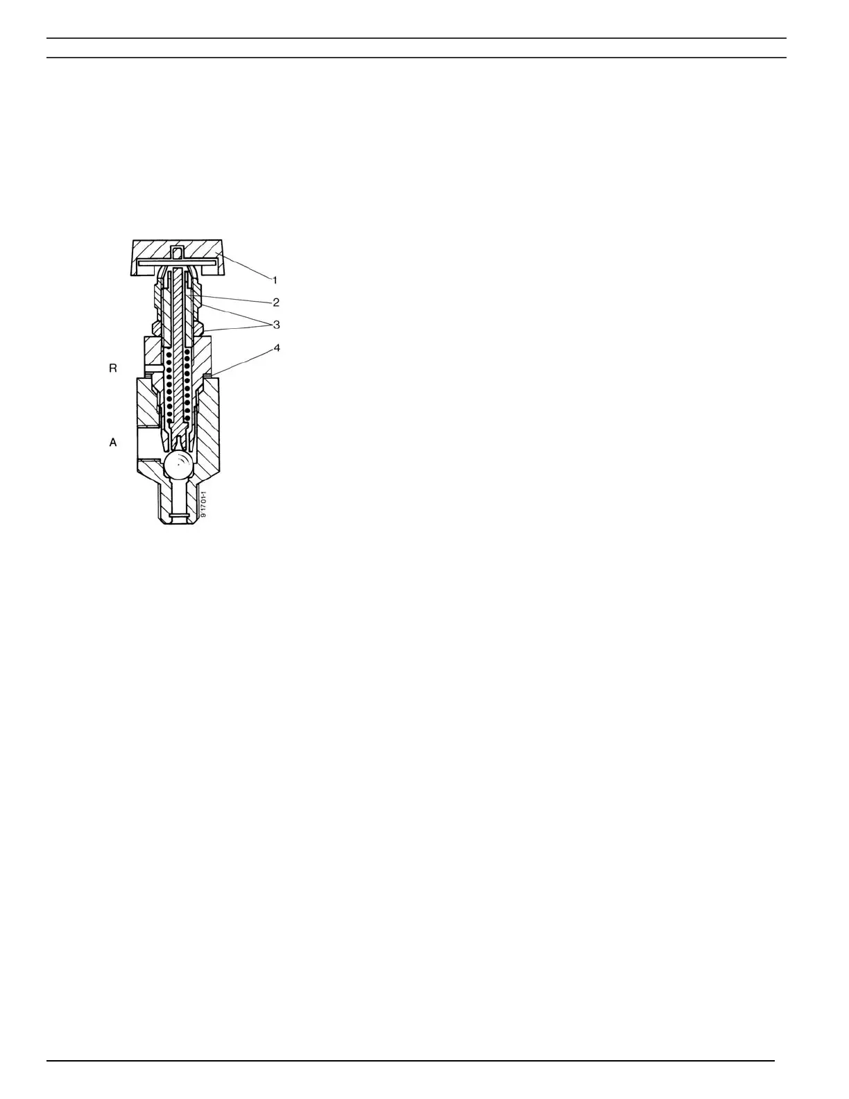
A Control air to unloader
R Vent hole
1 Unloading handle
2 Pressure adjusting screw
3 Nuts
4 Shims
Fig. 5.9 Pilot valve on LE/LT Trolley
Unload mechanism
The pilot valve is equipped with a hand-operated unload mechanism: by turning the red handle (1) 90
degrees, the plunger of the valve will be lifted, releasing the spring force. The air pressure from the
pulsation dampers will force down unloader plunger (12-Fig. 1.12), the compressor will run unloaded. By
turning handle (1) 90 degrees further, the plunger returns to its original position so that the pilot valve will
again unload and load the compressor at the pre-set pressures.
Setting of the pilot valve
The maximum pressure is controlled by adjusting screw (2):
- Loosen handle (1) and the two nuts (3).
- Turn the adjusting screw (2) clockwise to increase the maximum pressure.
- The pressure difference can be increased by removing one or more shims (4).
- Fit the two nuts (3) and handle (1) in their original position.
2920 1585 00 - 60 -
 Loading...