17
Logic Confi gurator
Back to the Logic Confi gurator sheet, where we now program the
second input signal, for the ”R” input of the gate. The signal Logic
digin 1 can be found in the ”Digital input” selection.
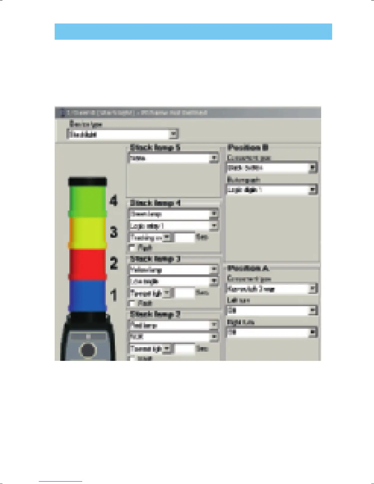
Go to Accessory setup and program the Stacklight. The illustration
shows that the output signal of our Logic Confi gurator sheet is called
Logic Relay 1. We give the ”button push” signal the name Logic digin
1, see below.
 Loading...