System 9 Installation and Operation
5
UniPak
®
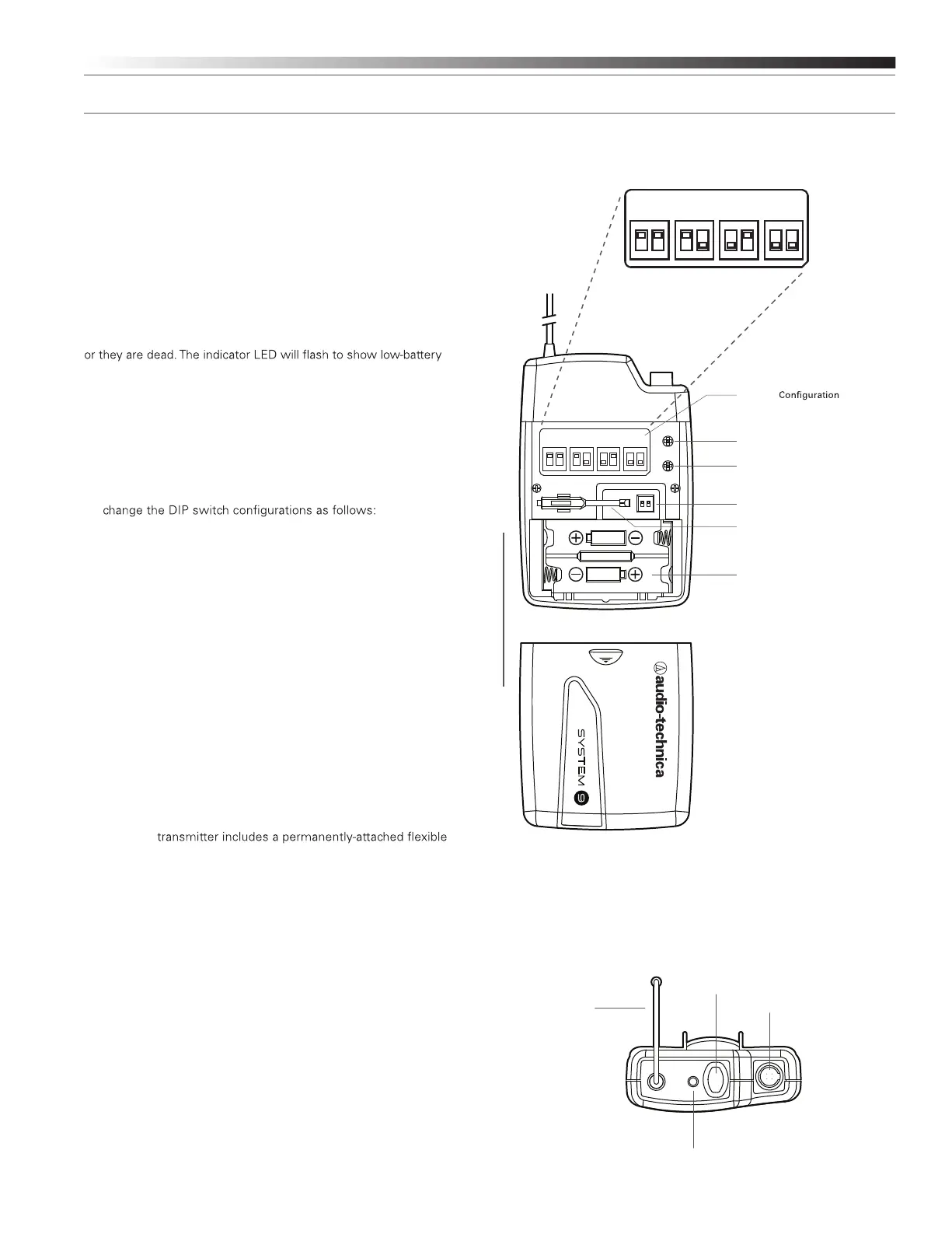
Transmitter Battery Installation
1. Slide off the battery cover as shown in Figure D.
2. Carefully insert two fresh AA alkaline batteries, observing polarity
markings.
3. Replace the battery cover (Fig. D).
UniPak
®
Transmitter Power/Mute/Battery Indicator
After the battery is installed, press and hold the power button until the
indicator LED turns green (Fig. E). If the indicator LED does not light up
when the power button is pressed, the batteries are installed incorrectly
condition.
UniPak
®
Transmitter Channel Selection
Before turning on the transmitter, use DIP Switches 1 and 2, located
inside the UniPak
®
Transmitter, to select the desired channel.
1. To access the DIP Switches, slide off the battery cover.
2. To achieve the desired channel, use the provided screwdriver to
Channel 1: Switches 1 and 2 “up”
Channel 2: Switch 1 “up”; Switch 2 “down”
Channel 3: Switch 1 “down”; Switch 2 “up”
Channel 4: Switches 1 and 2 “down”
3. Replace the battery cover.
UniPak
®
Transmitter Mute Function
With the transmitter on, a slight touch of the Power/Mute button will
toggle between muted and unmuted operation. Red indicator LED shows
muted operation. Green indicator LED shows unmuted operation.
UniPak
®
Transmitter Input Connection
Connect an audio input device (microphone or guitar cable) to the
audio input connector on the top of the transmitter. A number of
Audio-Technica professional microphones and cables are available
separately, pre-terminated with a UniPak
®
input connector (see
www.audio-technica.com).
UniPak
®
Transmitter Antenna
The UniPak
®
antenna. For best results, allow the antenna to hang freely and
full length from the transmitter. If the received signal is marginal,
experiment with different transmitter positions on your body or
instrument; or try repositioning the receiver. Do not attempt to
remove, replace or change the length of the transmitting antenna.
PUSH
L
INST
MIC
H
L H
LR6,AA
LR6,AA
1
ON
2
CHANNE L 1 CHANNE L 2 CHANNE L 3 CHANNE L 4
1
ON
2 1
ON
2 1
ON
2
Switch Conf iguration for Channel Selection
CHANNEL
1
ON
2
Figure E — UniPak
®
Transmitter
Channel Selection DIP Switches
Channel
Label
Antenna
Input
Connector
Power/Mute
Button
Screwdriver
Instrument Trimmer (INST)
Microphone Trimmer (MIC)
Indicator LED
(Power/Mute/Battery)
Battery Compartment
1
ON
2
CHANNEL 1 CHANNEL 2 CHANNEL 3 CHANNEL 4
1
ON
2 1
ON
2 1
ON
2
Switch Conf iguration for Channel Selection
Figure D — UniPak
®
Transmitter
 Loading...