p. 33/46
TLxx-MT-EN-04
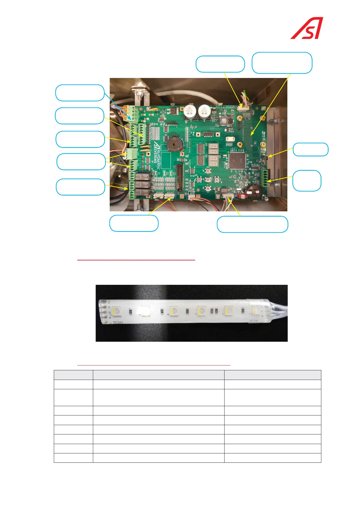
For complete information on the AS1635 circuit board, please refer to the technical manual for the product.
Angular sensor
Location for the AS1622
Ethernet circuit board
(optional)
USB port
RS232 and
RS485
CAN bus (for controlling the
motor circuit board)
Outputs to
pictograms
Relay outputs (3x)
Digital outputs
24 VDC for the
detection cells
Digital inputs
Power supply 24 VDC
Fig. 33 Control circuit board
7.4.3. functional pictogram (operating symbols)
The functional pictogram consists of 6 sets of 4 LEDs of different colours (GRBW) soldered on a flexible support glued
to the inside of the frame (double face tape):
Fig. 34 Electronic circuit of the functional pictogram
7.4.4. liSt of the electrical and electronic Sub-aSSemblieS
Reference Description Comment
1 Control logic circuit board AS1635 Without the female connectors
2 Angular sensor assembly with AS1637 circuit
board
With support and fixing screw
3 Power module 24VDC
4 Main circuit breaker
5 Electro-magnet assembly With support and end stop.
6 Functional pictogram (option) Circuit and connecting cable
7 Gear motor assembly
8 Motor control circuit board AS1636 (optional)

 Loading...