B-31
(A)
Photo
electric
sensor
(B)
Fiber
optic
sensor
(C)
Door/Area
sensor
(D)
Proximity
sensor
(E)
Pressure
sensor
(F)
Rotary
encoder
(G)
Connector/
Socket
(H)
Temp.
controller
(I)
SSR/
Power
controller
(J)
Counter
(K)
Timer
(L)
Panel
meter
(M)
Tacho/
Speed/ Pulse
meter
(N)
Display
unit
(O)
Sensor
controller
(P)
Switching
mode power
supply
(Q)
Stepper
motor&
Driver&Controller
(R)
Graphic/
Logic
panel
(S)
Field
network
device
(T)
Software
(U)
Other
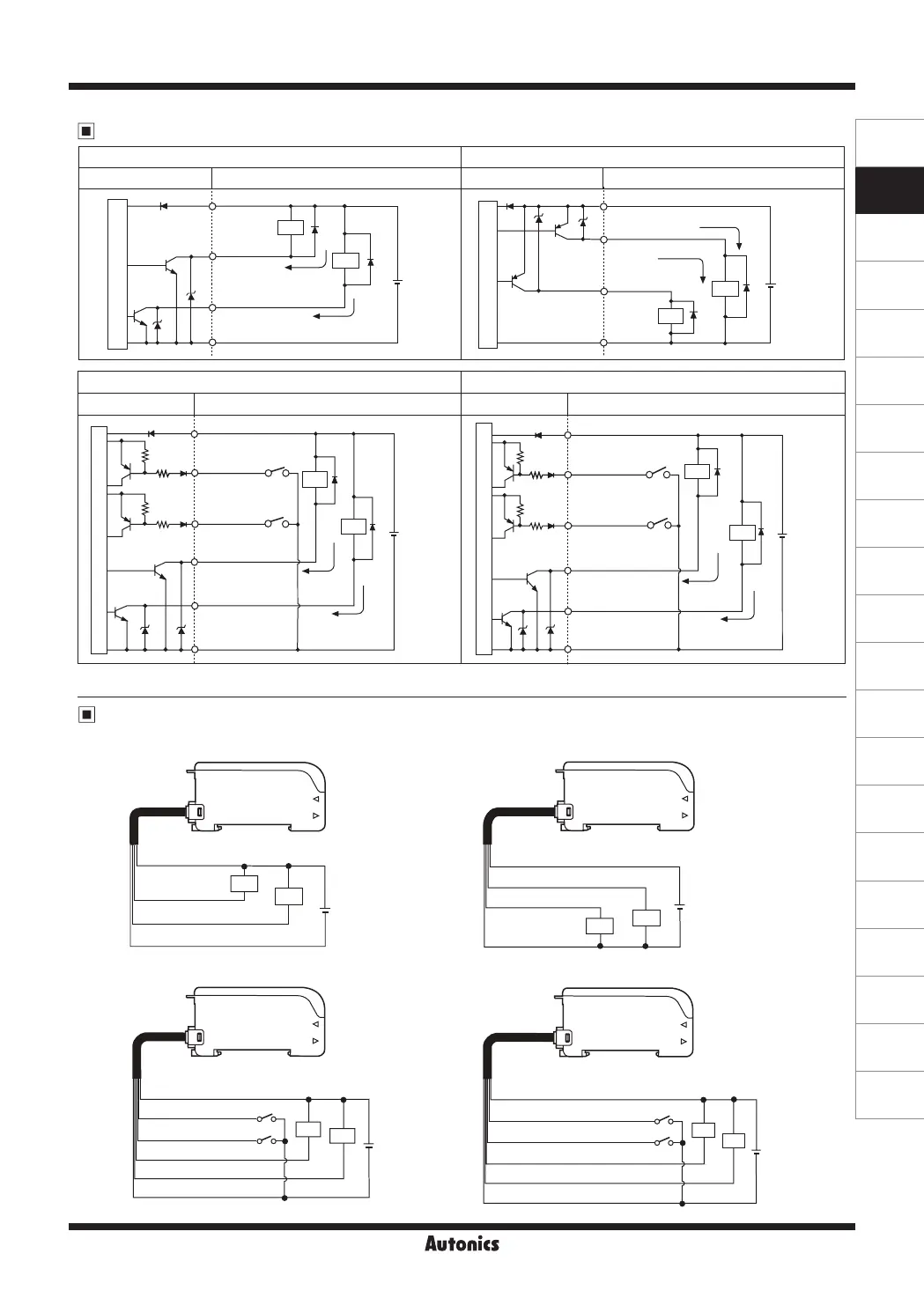
Fiber Optic Amplier
※
Connect Diode at external terminal for inductive load.
● BF4R / BF4G
● BF4R-E / BF4G-E
● BF4RP / BF4GP
● BF4R-R / BF4G-R
(Brown) +V
(Black) Control output
(White) Self-diagnosis output
(Blue) 0V
Load
Load
12-24VDC±10%
+
-
(Brown) +V
(Black) Control output
(White) Self-diagnosis output
(Blue) 0V
Load
Load
(Pink) External synchronization input
(Orange)
Emission disable input
12-24VDC±10%
+
-
(Black) Control output
(White) Self-diagnosis output
(Blue) 0V
(Brown) +V
Load
Load
12-24VDC±10%
+
-
(Brown) +V
(Black) Control output
(White) Self-diagnosis output
(Blue)0V
Load
Load
(Pink) ON input of remote sensitivity setting
(Orange)
OFF input of remote sensitivity setting
12-24VDC±10%
+
-
BF4R / BF4G BF4RP / BF4GP
Fiber optic sensor circuit Connection Fiber optic sensor circuit Connection
(Blue)0V
12-24VDC
12-24VDC
+
-
+
-
(Brown)+V
(Black)
Control output
(White)
Self-diagnosis output
Max. 50mA
Max. 100mA
※
※
Load
Load
Load
Load
(Blue)0V
(Brown)+V
(Black)Control output
(White)
Self-diagnosis
output
Max. 50mA
Max. 100mA
※
※
Main circuit
Main circuit
BF4R-E / BF4G-E BF4R-R / BF4G-R
Fiber optic sensor circuit
Connection
Fiber optic sensor circuit
Connection
12-24VDC
12-24VDC
+
-
+
-
(White)
Self-diagnosis output
(White)
Self- diagnosis output
(Brown)+V
(Brown)+V
(Pink)
(Pink)
(Orange)
(Orange)
※
Load
Load
Load
Load
※
(Black)
Control output
(Black) Control output
Max. 50mA
(Blue)0V
(Blue)0V
External
synchronization input
ON input of remote
sensitivity setting
Emission
disable input
OFF input of remote
sensitivity setting
Max.
100mA
※
※
Max. 50mA
Max. 100mA
Main circuit
Main circuit
Control output diagram
Connections
 Loading...