B-11
(A)
Photo
electric
sensor
(B)
Fiber
optic
sensor
(C)
Door/Area
sensor
(D)
Proximity
sensor
(E)
Pressure
sensor
(F)
Rotary
encoder
(G)
Connector/
Socket
(H)
Temp.
controller
(I)
SSR/
Power
controller
(J)
Counter
(K)
Timer
(L)
Panel
meter
(M)
Tacho/
Speed/ Pulse
meter
(N)
Display
unit
(O)
Sensor
controller
(P)
Switching
power
supply
(Q)
Stepping
motor&
Driver&Controller
(R)
Graphic/
Logic
panel
(S)
Field
network
device
(T)
Software
(U)
Other
Fiber Optic Amplier
①
⑤
④
③
②
②
①
6
12 1 2 7 8 9 10
11
5
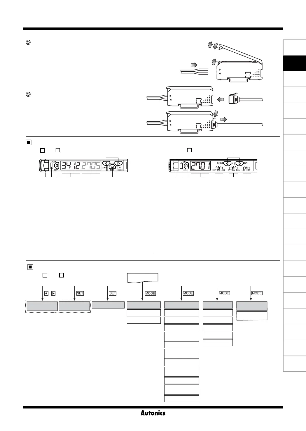
Fiber cable connection
● Lift up the protective cover
①
and push down the lock
lever to the direction of
②
to release the lock setting.
● Insert the cable to the direction of
③
with slightly
moving up and down 15˚, and gently press into the
unit until the cable is completely inserted (inserted
length: around 13mm).
● Lift up the lock lever to lock the lock setting
④
and
close the protective cover to
⑤
.
Wire connector connection
● Insert the connector into the amplifier unit until it clicks
into right position.
● When removing the connector, pull out the connector
to the
①
direction with pressing the lever downside to
the
②
direction.
Fiber cable connection
Parameter setting
1. Control output indicator(Red)
: Used to indicate control output provided by comparing SV and
actual incident light level
2. Sensitivity setting key
: Used to execute each operation and to set sensing sensitivity
3. PV display part (4 Digit, Red, 7 segments)
: Used to indicate incident light level and parameters
4. SV display part (4 Digit, Green, 7 segments)
: Used to indicate SV and setting data
5. Up/down key
● Used to up/down setting values
● Used to Fine-adjusting sensitivity
6. MODE key
● Used to enter into program mode / data Bank mode
● Used to move each parameter
112 2 3 4
7. PV/SV display part(4 Digit, Red, 7 segments)
: Used to indicate incident light level / SV and parameters
8. Response time setting switch : FAST, STD, LONG
9. Timer setting switch
: Used to select OFF Delay time (OFF, 10ms, 40ms)
10. Operation mode setting switch
: Used to select Light ON / Dark ON
11. Up/Down key
● Used to up/down setting values
● Used to enter into each mode
● Used to Fine-adjusting sensitivity
12. Lock lever
●
BF
5
-D1-
● BF5 -D1-
● BF5R-S1-
Press
, key
Press
key
Press
key
Press
key for 3 sec.
Press
key for 3 sec.
Press
key for 5 sec.
Press
key for 7 sec.
(Refer to B-12 to 14 page.)
Group teaching Monitoring mode
RUN mode
Data Bank mode
Initializing
function mode
Manual sensitivity
setting
Teaching sensitivity
setting
Copy
Program mode
Response time
Display function
Display direction
Time setting
Sensitive setting
mode
Energy saving
Channel
Lock setting
Timer operation
mode
Light ON/
Dark ON setting
Communication
enable/disable
High peak Data load
Initializing
function setting
Load all
Low peak Data save
Save all
(Refer toB-20page.)
(Refer to B-17 to 19 page.)
(Refer to B-15 to 17 page.)
(Refer to B-20 page.)
(Refer to B-14 to
15 page.)
[Installation]
[Removal]
 Loading...