Connections
Color Function
Brown +V
Blue 0 V
Black OUT 1
White OUT 2
Orange Option input / output
CIRCUIT
OCP
OCP
LOAD
LOAD
Output
impedance
Brown
Black
White
Blue
Orange
① ②
CIRCUIT
OCP
OCP
LOAD
LOAD
Output
impedance
Brown
Black
White
Blue
① ②
Orange
• ①: Option voltage / current output model, ②: Option external input model
• OCP (over current protection circuit)
• There is no short circuit protection circuit. Do not connect directly to power or capacitive loads.
• The control output is abnormal when the control output circuit is shorted or over current is
supplied.
• Pay attention to the input impedance of the connected device when using analog voltage
output. Be sure to the voltage drop due to the resistance of the wiring when extending the
wiring.
• Product • Instruction manual • Unit sticker
• Connector type: Bracket A / B, Connector wiring (PSO-C01)
• Cable type: Bracket C
• Front cover (PSO-P01), Panel bracket (PSO-B02 / B03)
• Pneumatic type: M5 gender
(PSO-Z01)
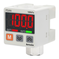
1
3
3
2
5
4
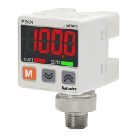
Run mode: Displays PV (present value), SV (setting
value)
Setting mode: Displays parameter and setting value
Turns ON when the corresponding control output
is ON.
4. [M] key
Enters parameter group, selects item and returns
run mode.
Sets preset of output operation mode, runs the
mode or changes parameter.
No mark: Pneumatic type (gas) / Back
D: Pneumatic type (gas) / Bottom
B: Fluid type (liquid, gas) / Back
L: Fluid type (liquid, gas) / Bottom
No mark: NPN open collector output
P: PNP open collector output
V: Voltage output
A: Current output
H: External input
Pressure
01
Static
0.0 to 100.0 kPa
1
0 to 1,000 kPa
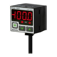
V01
Negative 0.0 to -101.3 kPa
C01
Compound -101.3 to 100.0 kPa
Medium
Port
Pneumatic Fluid
○ ○
○ -
○ ○
- ○
- ○
No mark: Cable type (fluid type)
C: Connector type
This is only for reference, the actual product does not support all combinations.
For selecting the specied model, follow the Autonics website.
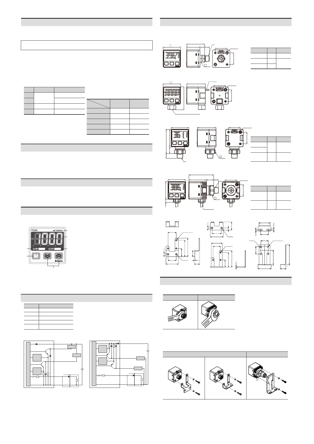
Installation
Spanner: 12 mm
Spanner: 17 mm
Connect the metal part with a
spanner so that no large force is
applied to the unit body.
(tightening torque: ≤ 10 N m, it may
cause malfunction.)
Bracket
Use spring washers and hexagon wrench bolts (tightening torque: ≤ 3 N m) to select
and install a bracket suitable for your environment.
• Bracket A • Bracket B • Bracket C
• Do not pull the wiring with a force of more than 30 N.
Dimensions
• Unit: mm, For the detailed drawings, follow the Autonics website.
30
20
2-M3
20
22.8 7.9 A
B
30.7
12
Port A B
Rc1/8 0
-
NPT1/8 0
Inner M5
tap
R1/8 8
30
39
20
20
2-M3
32
cable
Rc1/8(standard), NPT1/8
20
2-M3
20
32
17
30
41.3
A
30
11.3
B
Port A B
R1/8
8
Inner M5
tap
NPT1/8
7/16-
20UNF
11 -
30
30
5.1
20
2-M3
20
42.3
B
30
12.3 A
Ø4, 3m
17
Port A B
R1/8 8
Inner M5
tap
9/16-
18UNF
15.4 -
Bracket A Bracket B Bracket C
20
20
30
20
40
45
15
4.2
1.6
13
3-Ø3.2
Ø4.2
20
40
45
1.6
20
25
30
35
3-Ø3.2
4.2
6
22
Ø4.2
4-Ø3.2
Ø22
20
20
40
36
55
15
22
3.5
4.2
30
 Loading...