Line of Sight Infrared Hydrocarbon Gas Detector AutroPath HC800 , 116-P-HC800/IGB, Rev. A, 2016-03-03
P/N 95-8744, v4.2 , rev. 3/16
Autronica Fire and Security AS
Page 10
STATUS AND FAULT INDICATION
Status and fault conditions are indicated using the 4–20
mA analog signal output. Signaling modes include two
predefined modes, and a user defined mode for third
party compatibility. The user defined mode allows users
to define a mA output level (range 1.0 - 3.6 mA) for
each of the three status / fault categories: configuration,
advisory, and detection disabled. Refer to Table 4 for
status indications and Table 5 for fault conditions.
Status and fault indication configuration options can
be changed via HART or Modbus communication.
(Refer to the “Troubleshooting” section for additional
information regarding fault identification.)
NOTE
Transmitter warm-up and fault conditions are
indicated by a solid yellow LED, and diagnostics
can be performed using HART or Modbus
communication. The receiver will continue to
perform its safety function, and will indicate
a fault status if normal operation has been
compromised.
If a transmitter fault occurs, perform normal
maintenance and ensure correct input voltage
at the device. If normal operation cannot be
restored, return the device to the factory.
SpEcificationS
OPERATING VOLTAGE (Both Modules)—
24 Vdc nominal. Operating range is 18 to 30 Vdc.
Ripple cannot exceed 0.5 volts P-P.
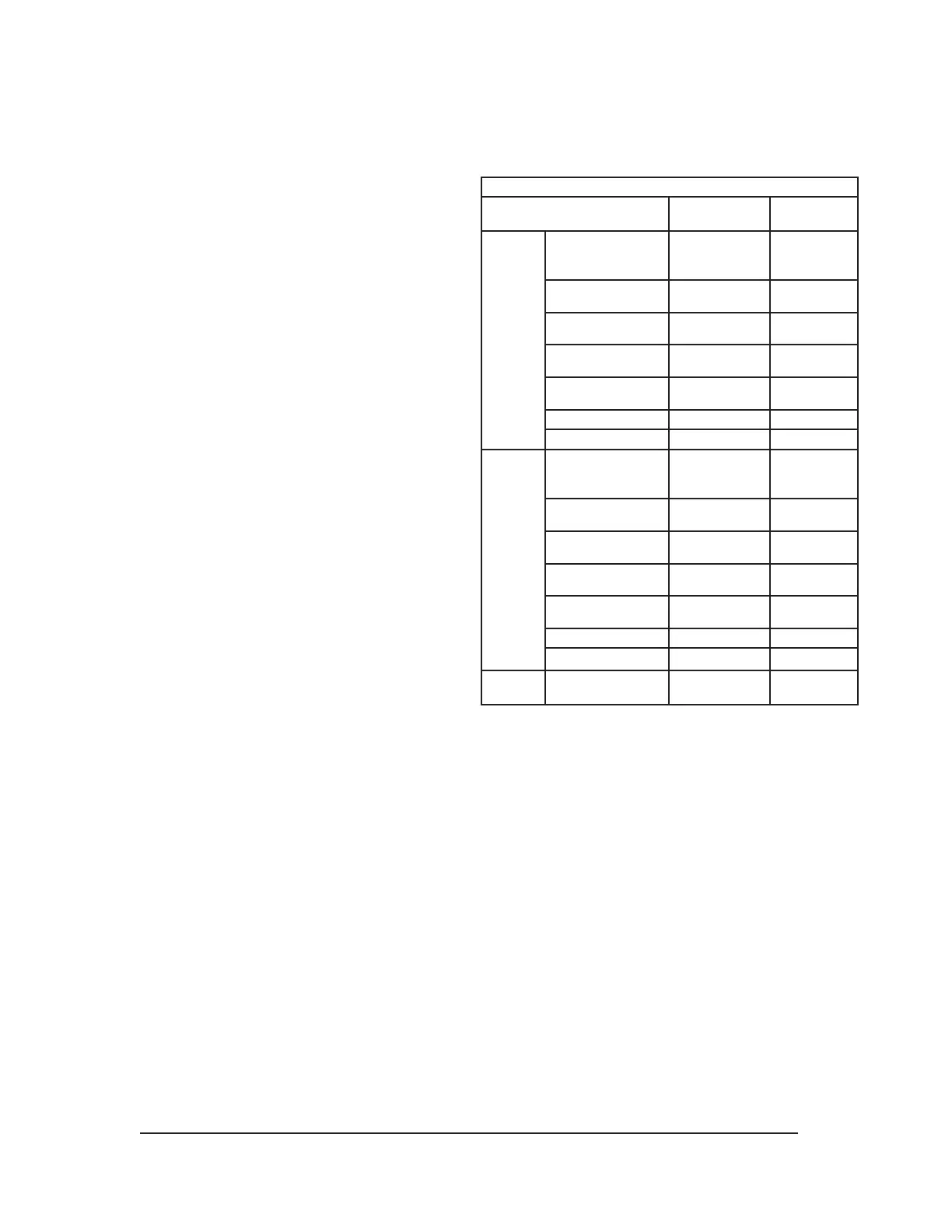
POWER CONSUMPTION—
Power Consumption (Watts)
Transmitter
Maximum
Receiver
Maximum
@ 24
VDC
Total Unit,
No Heaters
or Relays
6.5 2.6
30% Heater Only 1.4 1.1
50% Heater Only 2.5 2.0
70% Heater Only 3.5 2.7
100% Heater Only 4.2 3.3
Relay Only N/A 1.2
Total Unit, Max 10.7 7. 2
@ 30
VDC
Total Unit,
No Heaters
or Relays
6.5 2.9
30% Heater Only 2.3 1.8
50% Heater Only 4.2 3 .1
70% Heater Only 5.9 4.2
100% Heater Only 7. 2 5.1
Relay Only N/A 1.2
Total Unit, Max 13.7 9.3
@ 33
VDC*
Total Unit, Max 16.0 10.0
* Per regulatory approval requirements, the unit power consumption was
measured at 33 VDC input voltage
(10% above claimed range) and results listed on the product label.
TRANSMITTER LAMP—
Xenon flashlamp, field-replaceable module
(10 yr warranty).
WARMUP TIME—
15 seconds minimum, 150 seconds maximum from
power-up, depending upon alignment accuracy.
CURRENT OUTPUT—
Linear 4–20 mA (isolated/non-isolated) rated at 600
ohms maximum loop resistance @ 24 Vdc operating
voltage, with the ability to go below 4 mA to indicate a
fault condition.
 Loading...