AUX DC Inverter Free Match 50HZ R32
217
Part13 Trouble Shooting
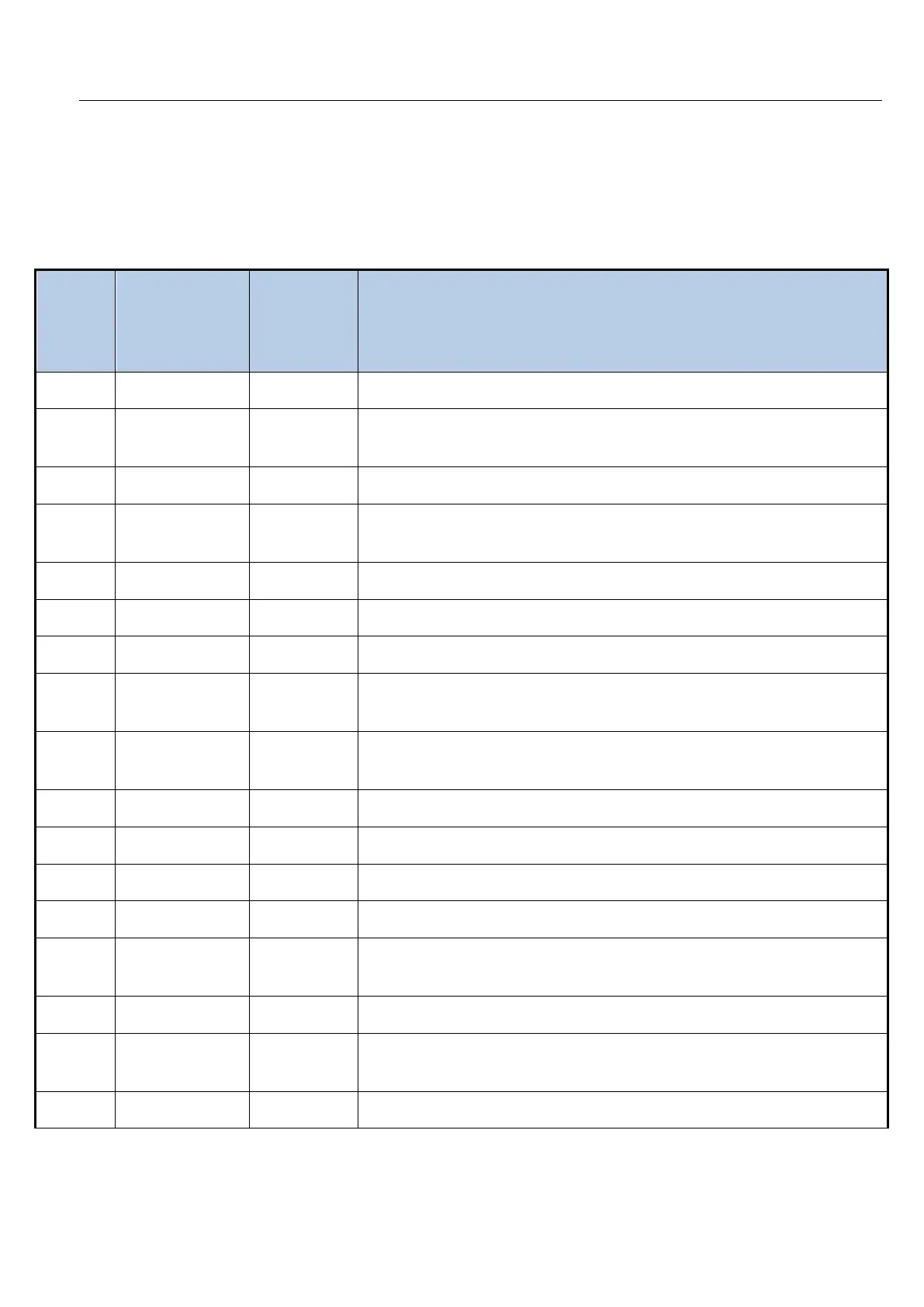
1. Failure code display
NO
CODE
(display
board)
CODE
(wired
controller)
DESCRIPTION
Fault with the over-electric current protection
2 L3 C3
Fault with the Compressor Power supply Phase deficiency
protection
Fault with the inverter module protection(IPM)
4 E1 E1
Fault with the room temperature sensor(Tico) on the indoor
unit
Fault with the temperature sensor(Tcm) on the outdoor unit
Fault with the temperature sensor(Ticm) on the indoor unit
Fault with the Fan motor of indoor unit
8 E5 E5
Communication error between the outdoor unit and the indoor
unit
9 E8 E8
Communication error between the display board and PCB of
the indoor unit
Fault with the Fan motor of outdoor unit
Fault with the inverter module protection on the outdoor unit
Fault with the compressor start
fault with the discharge temperature sensor
14 F6 F6
Fault with the Envirol temperature sensor(Tao) on the outdoor
unit
Fault with the over-voltage or low voltage protection
16 F8 F8
Communication error between the driver PCB and main PCB
of the outdoor unit
Fault with the outdoor unit EPROM
 Loading...