5
Catalog
listing
NPN HP7-P11 HP7-T51
HP7-T11 (Red)
HP7-T21 (Infrared)
HP7-T41 HP7-A13 HP7-A43 HP7-D23 HP7-D63 HP7-C11S
PNP HP7-P12 HP7-T52
HP7-P51
HP7-P52
HP7-T12 (Red)
HP7-T22 (Infrared)
HP7-T42 HP7-A14 HP7-A44 HP7-D24 HP7-D64 HP7-C12S
Detection
method
Retroreflective
*2 Thru-scan Diffuse-scan
Retroreflective transparent
object detection
Power supply
10.2 to 26.4 Vdc (Ripple 10% max.)
Power
consumption
− −−
14 mA max.
22 mA max.
25 mA max. (Red)
30 mA max. (Infrared)
32 mA max. 14 mA max. 17 mA max.
17 mA max.
15 mA max.
Scanning
distance
5 m (with
FE-RR8
reflector)
4 m 15 m 30 m 0.5 m 1 m 100 mm 50 mm
0.05 to 0.5 m
(when combined with
FE-RR17C reflector)
Target object
Opaque object 80 mm
dia. min(with
FE-RR8
reflector)
Opaque object 12 mm dia. min.
Standard target object: 200 × 200 mm
paper, 90 % reflectivity
10% light blockage or more,
50 × 50 mm or more
(when combined with
FE-RR17C reflector)
Differential travel
20% max. (at rated scanning distance)
Operation mode
Light-operate / Dark-operate selectable by operation button
Output mode
*1
NPN open collector / PNP open collector
Control output
Switching current: preleaded. Preleaded connector type 100 mA (Resistance load)
M8 connector type and low-temperature cable type 50 mA (Resistance load)
Output withstand voltage: 30 V
Residual voltage: 2 V or lower (at switching current of 100 mA/50 mA),
1.1 V or less (at switching current below 10 mA)
Switching current: 50 mA or
lower (Resistive load)
Output withstand voltage: 30 V
Residual voltage: 1 V or less
Response time
*3
1 msec
1 msec (Different frequency model: 3 ms)
1 msec 1 msec
Light source
Red, 4 elements
(Wavelength approx.
645 nm)
Red, 4
elements
(Wavel-
ength
approx.
645 nm)
Red, 4 elements
(Wavelength
approx. 645 nm)
Infrared
(Wavelength
approx. 860 nm)
Infrared
(Wavel-
ength
approx.
860 nm)
Red, 4
elements
(Wavel-
ength
approx.
645 nm)
Infrared
(Wavelength approx. 860 nm)
Red, 4 elements
(Wavelength approx.
645 nm)
Scanning angle
0.5 to 10°
3 m (with
FE-RR8
reflector)
2 to 20° Switch: 0.5° to 10°
Indicator
Output ON: orange indicator ON. At stable light and stable dark: green indicator
Thru-scan emitter: power indicator, 30 m thru-scan receiver: light-operated indicator on front
Ambient light
immunity
Incandescent lamp: 10,000 lux max. Sunlight: 40,000 lux max. HP7-T_, HP7-P_, HP7-C_: Minimum angle of incidence of surrounding light = 5°
HP7-A_: Minimum angle of incidence of surrounding light = 15° HP7-D_:Figures apply to indirect illumination.
Operating
temperature
-30 to + 55˚C (without freezing or condensation)
*6
-10 to + 55˚C (without freezing
or condensation)
*6
Storage temperature
-40 to + 70˚C (without freezing or condensation)
Operating humidity
35 to 85% RH (without freezing or condensation)
Insulation resistance
20M min. (at 500Vdc)
Dielectric strength
1,000Vac 50/60Hz for one minute between electrically live metal and case
Vibration resistance
10 to 55Hz, 1.5 mm peak-to-peak amplitude, 2 hours each in X, Y, and Z directions
Shock resistance
500 m/s 10 times each in X, Y and Z directions
Sensitivity adjustment
Operation button
Protective structure
IP67 (IEC standard)
Wiring method
HP7-_ _: preleaded 2 m, HP7-_-L050: preleaded 5 m, HP7-_-C003: M12 preleaded connector 30 cm, HP7-_-T: M8 connector
Circuit
protection
Error prevention circuit at power on (max. 60 ms)
Full wiring error protection
Error prevention circuit at
power on (max. 80 ms)
Power supply reverse polarity
protection, output
short-circuit protection
Interference
suppression*
5
Diffuse-scan, retroreflective, retroreflective transparent object detection models up to 2 units.
Thru-scan models with different frequencies, up to 2 units. Thru-scan models with mutual interference prevention filter*4
(for red), up to 2 units.
Different frequency models + mutual interference prevention filters (for red), up to 4 units.
*1. An FET is used for output
*2. Retroreflective switches feature polarizing filters; however, performance may be affected by highly reflective objects and objects that interfere with polarization.
*3. Response time may be longer if affected by light from other switches.
*4. Mutual interference protection filters are for red light source.
*5. Avoid operating diffuse-scan switches head-on when using gang mounting.
*6. In a low-temperature environment (0° or below), the standard cable will harden. Low temperature cables are available. Contact our branch or sales office to order.
(Not available for HP7-C1_S.)
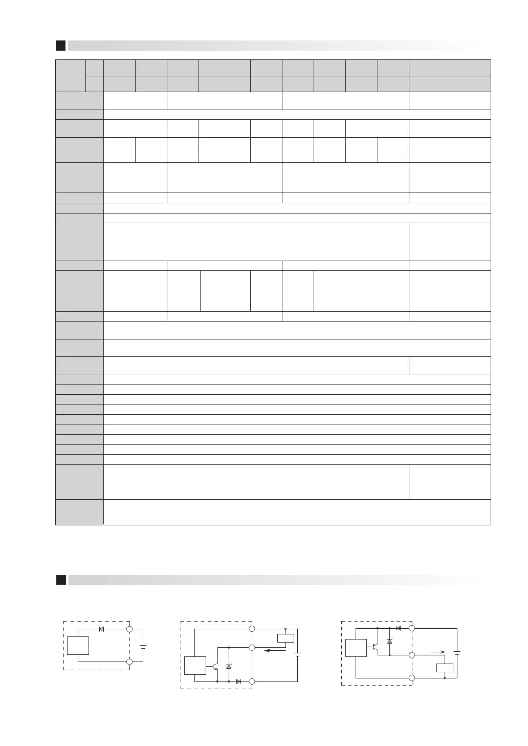
Thru-scan emitter (NPN output type)
Polarized retroreflector model,
Thru-scan receiver, Diffuse-scan mode
(PNP output type)
Polarized retroreflector model,
Thru-scan receiver, Diffuse-scan model
Main
circuit
Control output
Brown
Load
100 mA max.
10.2 to
26.4
Vdc
Black
Blue
1
4
3
Main
circuit
Brown
10.2 to
26.4
Vdc
Blue
1
3
Main
circuit
Control output
Brown
Load
100 mA max.
10.2 to
26.4
Vdc
Black
Blue
1
4
3
OUTPUT CIRCUIT DIAGRAM
(Note that a FET is used for output)
−
 Loading...