INSTRUCTIONS
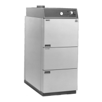
Solo Innova
Page 21
4.2
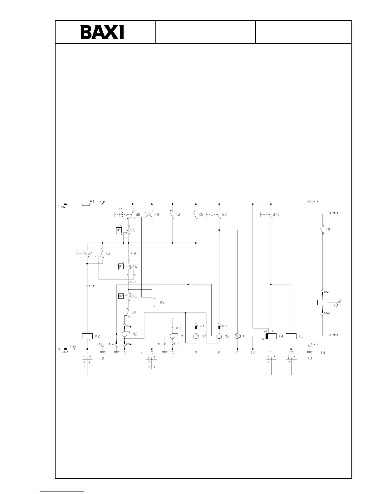
Circuit diagrams
4.2.1 Electrical connection
Electrical connection via the cable provided. Description of functions see Section 3.7.2.
4.2.2 Circuit diagram legend
Fig. Fig. Fig. F ig.
B12 H Overheating thermostat 100°C
B15 – Min. thermostat 90°C
B16 I Thermostat 85-93°C
L – Phase 230 V
F1 D Fuse 6.3 A (5 x 20 mm)
H2 – In-operation light circulation pump (S2)
H4 – In-operation light fan switch (S4)
K2 – Auxiliary relay holding current circuit
K4 – Time relay
K10 O Switch for door interlock
M2 – Circulation pump, system (optional extra)
M6 – Fan
M7 – Charging pump for buffer tank (optional
extra)
N – Neutral conductor
S2 E Switch for circulation pump (M2), system
S4 F Fan switch
S7 N Reset switch for fan
W1 – Connection cable
W3 – Cable for circulation pump, system
W7 – Cable for fan
W10 – Earth cable
W11 – Cable for buffer tank charging pump
W13 – Cable for door interlock
X1 – Terminal strip for various connections
Y3 – Solenoid coil
4.2.3 Wiring diagram
Fig. 4.2.3
 Loading...