Installation Instructions
8 C9900-P223 / C9900-P224
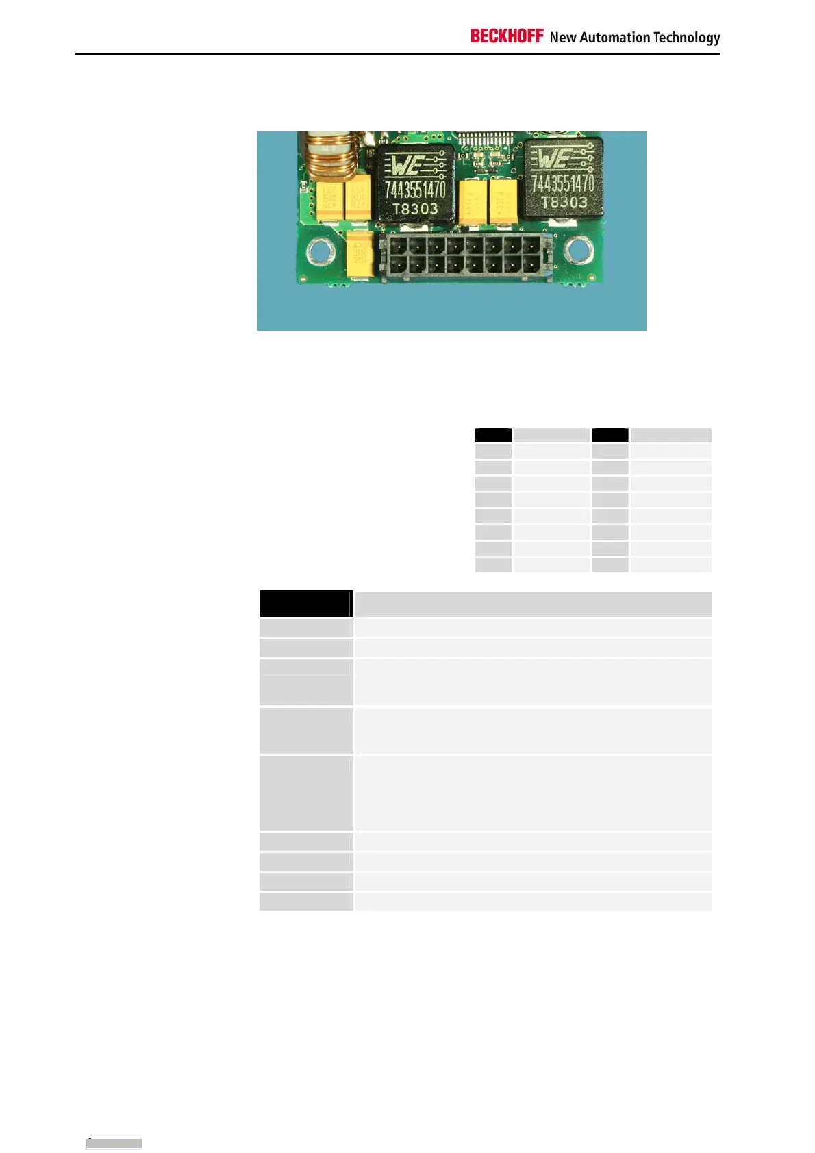
Connection with the motherboard
Pin strips
on the output side
Connection with the
motherboard
The power supply unit is connected with the motherboard according to the
installation instructions of the board.
Pin assignment
Pin assignment of the
output connector
Connector: MOLEX-34045-1613
Pin Signal Pin Signal
1
RX
9
TX
2
PS_ON
10
Powergood
3
ATXSW
11
5 V Standby
4
+ 12V
12
+ 12V
5
GND
13
GND
6
GND
14
GND
7
+ 5V
15
+ 5V
8
+ 5V
16
+ 5V
Signal description
Function Description
RX TTL-input RS232-interface (view from power supply)
TX TTL-output RS232- interface (view from power supply)
PS_ON TTL-input voltage request from motherboard
High -> motherboard reports "stand-by"
Low -> motherboard reports "connect voltage"
Powergood TTL-output
Low -> voltages at motherboard connector not o.k.
High -> voltages at output connector o.k.
ATXSW TTL-output
Enables the Power supply to boot the Industrial PC via the ATX-
switch:
Low -> motherboard logic shall open the ATX-switch
HIGH -> motherboard logic shall close the ATX-switch
GND ground
VCC +5V 20A
+12V +12V 5A
5V-Standby +5V 1A standby voltage
Downloaded from Arrow.com.Downloaded from Arrow.com.Downloaded from Arrow.com.Downloaded from Arrow.com.Downloaded from Arrow.com.Downloaded from Arrow.com.Downloaded from Arrow.com.Downloaded from Arrow.com.Downloaded from Arrow.com.Downloaded from Arrow.com.
 Loading...