
Do you have a question about the Beckhoff CX8080 and is the answer not in the manual?
| Product Type | Embedded PC |
|---|---|
| CPU Cores | 1 |
| Ethernet Ports | 2 |
| USB Ports | 2 |
| Power Supply | 24 V DC |
| Protection Class | IP20 |
| Weight | 0.5 kg |
| Storage | 4 GB |
| Protocols | EtherCAT, Modbus TCP |
| Operating Temperature | -25…+60 °C |
| Storage Temperature | -40…+85 °C |
| Relative humidity | 95% (non-condensing) |
| EMC immunity/emission | EN 61000-6-2, EN 61000-6-4 |
| Dimensions (W x H x D) | 100 mm x 100 mm x 75 mm |
| Processor | ARM Cortex-A8 |
| Operating System | Windows Embedded Compact |
| Vibration/shock resistance | EN 60068-2-6/EN 60068-2-27 |
Information for trained specialists and safety notes.
Safety regulations, exclusion of liability, and symbol explanations.
Version history and status of the documentation.
Overview of the CX80xx device family, features, and architecture.
Introduction to the CX8080, its interfaces, and key features.
Detailed technical specifications for the CX8080.
Information about MicroSD card options and usage.
Instructions for mounting the CX80xx devices.
Procedures and guidelines for wiring the CX80xx.
Steps for changing the internal battery.
Configuration of the address switch for device identification.
Steps for setting the IP address via DHCP or static configuration.
Configuration and management of the CX80xx operating system.
Operation and configuration of K-bus and E-bus terminals.
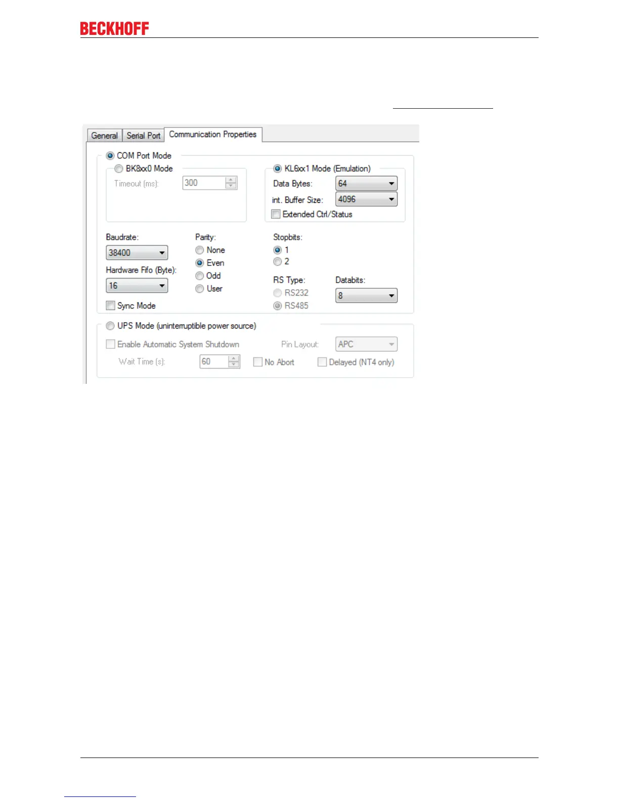
Configuration and programming of the RS232 and RS485 serial interfaces.
Accessing diagnostic webpages and remote control features.
Reading and setting the real-time clock using function blocks.
Explanation of the 1-second UPS for persistent data saving.
Monitoring and managing CPU load on the CX80xx devices.
Information about the available PLC libraries for CX80xx devices.
Details on the Seconds UPS function block and its operation.
Explanation of diagnostic LEDs on the CX8080 and their functions.
Using the F_CX80xx_ADDRESS function for diagnostics.
Programming the RS232/485 interface using KL6xx1 mode.
Introduction to Ethernet technology and its applications.
Example of network topology for Ethernet connections.
Overview and protocol details of Modbus TCP communication.
Information on the TCP/IP server for custom protocols.
Explanation of ADS communication protocol within TwinCAT.
Overview of the RS232/RS485 interface capabilities and limitations.
Description of the ZB3180 D-sub connector accessory.
Explanation of diagnostic LEDs for Ethernet interface and LED coupler.
Description of LEDs for power supply terminals in K-bus and E-bus operations.
Table of K-bus error codes, arguments, descriptions, and remedies.
Essential components and steps for initial setup and configuration.
Procedures for updating the device image via USB or MicroSD card.
Information on obtaining technical support and service from Beckhoff.


