Ethernet
6.2.3 Mapping between Modbus and ADS
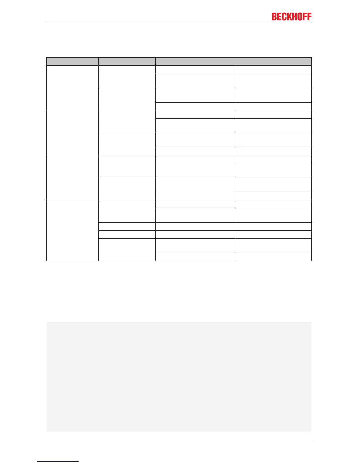
The standard mapping of the server is illustrated in the following tables for the first runtime system:
Modbus ranges Modbus address ADS range
Digital inputs 0x0000 - 0x7FFF Index group Index offset
0xF021 - process image of the
physical inputs (bit access)
0x0
0x8000 - 0x80FF Name of the variables in the
PLC program
Data type
.mb_Input_Coils ARRAY [0..255] OF BOOL
Digital outputs
(coils)
0x0000 - 0x7FFF Index group Index offset
0xF031 - process image of the
physical outputs (bit access)
0x0
0x8000 - 0x80FF Name of the variables in the
PLC program
Data type
.mb_Output_Coils ARRAY [0..255] OF BOOL
Input registers 0x0000 - 0x7FFF Index group Index offset
0xF020 - process image of the
physical inputs
0x0
0x8000 - 0x80FF Name of the variables in the
PLC program
Data type
.mb_Input_Registers ARRAY [0..255] OF WORD
Output registers 0x0000 - 0x2FFF Index group Index offset
0xF030 - process image of the
physical outputs
0x0
0x3000 - 0x5FFF 0x4020 - PLC memory area 0x0
0x6000 - 0x7FFF 0x4040 - PLC data area 0x0
0x8000 - 0x80FF Name of the variables in the
PLC program
Data type
.mb_Output_Registers ARRAY [0..255] OF WORD
The server maps this to the individual ADS ranges and enables access to the physical process image and
the PLC flag ranges.
The configurator enables the adaptation of the setting.
Default XML
The standard configuration looks like this:
<Configuration>
<!--ModbusTCPport,default=502-->
<Port>502</Port>
<!--optionalIPconfigurationforModbusTCPserver-->
<IpAddr/>
<Mapping>
<InputCoils>
<MappingInfo>
<!--AdsPort:TwinCAT2PLC1=801,PLC2=811...-->
<AdsPort>801</AdsPort>
<StartAddress>0</StartAddress>
<EndAddress>32767</EndAddress>
<!--IndexGroup61473=0xF021->physicalplcinputs%IX-->
<IndexGroup>61473</IndexGroup>
<!--Bitoffset-->
<IndexOffset>0</IndexOffset>
</MappingInfo>
<MappingInfo>
<AdsPort>801</AdsPort>
<!--Modbusinputcoils-->
<StartAddress>32768</StartAddress>
<EndAddress>33023</EndAddress>
CX808050 Version: 1.0.0