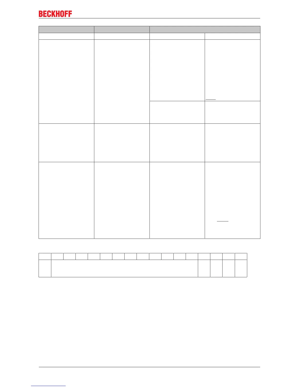
EasyManua.ls Logo

Beckhoff CX8080 User Manual

Beckhoff CX8080
67 pages
To Next Page IconTo Next Page
To Previous Page IconTo Previous Page
Page #43 background imageLoading...
Page #43 background image
Programming
Bit Name Comment
CW.3 Reserved - -
CW.2 IR
(InitRequest)
1
bin
The controller requests
terminal for initialization.
The send and receive
functions are blocked, the
FIFO indicators are reset,
and the interface is again
initialized with the value.
The interface
acknowledges completion
of the initialization via bit
SW.2 (IA).
0
bin
The controller once again
requests the interface to
prepare for serial data
exchange.
CW.1 RA
(ReceiveAccepted)
toggle The controller
acknowledges receipt of
data by changing the state
of this bit. Only then new
data can be transferred
from the interface to the
controller.
CW.0 TR
(TransmitRequest)
toggle Via a change of state of
this bit the controller
notifies the interface that
the DataOut bytes contain
the number of bytes
indicated via the OL bits.
The interface
acknowledges receipt of
the data in the status byte
via a change of state of
word SW.0 (TA). Only
now new data can be
transferred from the
controller to the interface.
Table2: Status word
Bit 15 14 13 12 11 10 09 08 07 06 05 04 03 02 01 00
Nam
e
Length of data in the buffer ((IL bits) BUF
_F
IA RR TA
Legend
CX8080 43Version: 1.0.0
Question and Answer IconNeed help?

Do you have a question about the Beckhoff CX8080 and is the answer not in the manual?

Beckhoff CX8080 Specifications

General IconGeneral
Product TypeEmbedded PC
CPU Cores1
Ethernet Ports2
USB Ports2
Power Supply24 V DC
Protection ClassIP20
Weight0.5 kg
Storage4 GB
ProtocolsEtherCAT, Modbus TCP
Operating Temperature-25…+60 °C
Storage Temperature-40…+85 °C
Relative humidity95% (non-condensing)
EMC immunity/emissionEN 61000-6-2, EN 61000-6-4
Dimensions (W x H x D)100 mm x 100 mm x 75 mm
ProcessorARM Cortex-A8
Operating SystemWindows Embedded Compact
Vibration/shock resistanceEN 60068-2-6/EN 60068-2-27

Summary

1 Foreword

1.1 Notes on the documentation

Information for trained specialists and safety notes.

1.2 Safety instructions

Safety regulations, exclusion of liability, and symbol explanations.

1.3 Documentation issue status

Version history and status of the documentation.

2 Product overview

2.1 CX80xx - System overview

Overview of the CX80xx device family, features, and architecture.

2.2 CX8080 - Introduction

Introduction to the CX8080, its interfaces, and key features.

2.3 Technical data

Detailed technical specifications for the CX8080.

2.4 CX80xx - MicroSD cards

Information about MicroSD card options and usage.

3 Mounting and wiring

3.1 Mounting

Instructions for mounting the CX80xx devices.

3.2 Wiring

Procedures and guidelines for wiring the CX80xx.

3.3 Changing the battery

Steps for changing the internal battery.

4 Parameterization and commissioning

4.1 Address switch

Configuration of the address switch for device identification.

4.2 Setting the IP adress

Steps for setting the IP address via DHCP or static configuration.

4.3.1 CX80xx - Operating system

Configuration and management of the CX80xx operating system.

4.3.2 Power supply terminal

Operation and configuration of K-bus and E-bus terminals.

4.3.3 RS232/485

Configuration and programming of the RS232 and RS485 serial interfaces.

4.3.4 Web Services

Accessing diagnostic webpages and remote control features.

4.3.5 Real Time Clock (RTC)

Reading and setting the real-time clock using function blocks.

4.3.6 1-second UPS (Uninterruptible Power Supply)

Explanation of the 1-second UPS for persistent data saving.

4.3.7 CPU load

Monitoring and managing CPU load on the CX80xx devices.

5 Programming

5.1 Library for CX80xx

Information about the available PLC libraries for CX80xx devices.

5.2 Seconds UPS

Details on the Seconds UPS function block and its operation.

5.3 CX8080 LED

Explanation of diagnostic LEDs on the CX8080 and their functions.

5.4 Diagnostics

Using the F_CX80xx_ADDRESS function for diagnostics.

5.5 RS232/RS485

Programming the RS232/485 interface using KL6xx1 mode.

6 Ethernet

6.1 System introduction

Introduction to Ethernet technology and its applications.

6.1.2 Topology example

Example of network topology for Ethernet connections.

6.2 Modbus TCP

Overview and protocol details of Modbus TCP communication.

6.3 TCP/IP

Information on the TCP/IP server for custom protocols.

6.4 ADS-Communication

Explanation of ADS communication protocol within TwinCAT.

7 Serial interface

7.1 RS232/RS485 system overview

Overview of the RS232/RS485 interface capabilities and limitations.

7.2 ZB3180

Description of the ZB3180 D-sub connector accessory.

8 Error handling and diagnosis

8.1 Diagnostic LEDs

Explanation of diagnostic LEDs for Ethernet interface and LED coupler.

LED power supply terminal

Description of LEDs for power supply terminals in K-bus and E-bus operations.

K-bus error code

Table of K-bus error codes, arguments, descriptions, and remedies.

9 Appendix

9.1 First steps

Essential components and steps for initial setup and configuration.

9.2 Image Update

Procedures for updating the device image via USB or MicroSD card.

9.3 Support and Service

Information on obtaining technical support and service from Beckhoff.

Related product manuals