EasyManua.ls Logo

Beckhoff CX90 0 Series User Manual

Beckhoff CX90 0 Series
61 pages
To Next Page IconTo Next Page
To Previous Page IconTo Previous Page
Page #21 background image
Product overview
Embedded PC 19
These interfaces are connected to an internal 3-port switch and offer a simple option for creating a line topology
without the need for additional Ethernet switches.
Basic CPU module with DVI/USB interface:
In addition to the two Ethernet ports, this basic module also features DVI/USB interfaces. The pin assignment of the
basic CPU module with two USB and a DVI-I interface is explained under the associated CX9000-N010 system
interface.
Applicable to all basic CPU modules:
LED
The green power LED (PWR) is on if the basic CPU module is connected correctly to a live power supply unit.
Compact Flash slot
Further information can be found under Compact Flash slot.
Question and Answer IconNeed help?

Do you have a question about the Beckhoff CX90 0 Series and is the answer not in the manual?

Beckhoff CX90 0 Series Specifications

General IconGeneral
BrandBeckhoff
ModelCX90 0 Series
CategoryController
LanguageEnglish

Summary

Foreword

Safety Instructions and Operator Responsibilities

Covers safety rules, user diligence, and national regulations.

Product Overview

System Overview and I/O Systems

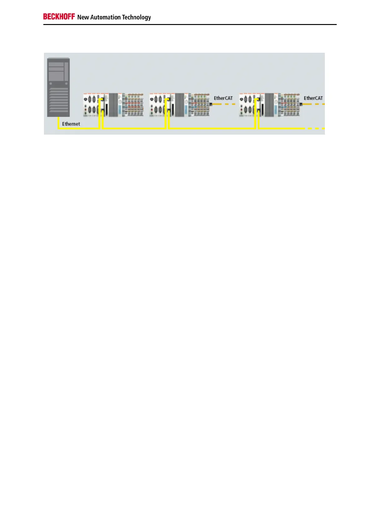
General system description, EtherCAT/K-Bus, interfaces, software.

Basic Modules Description

Details the CX90x0 Ethernet Controller and its versions.

Technical Data for CX9000 Models

Specific technical specifications for CX9000 E-bus and K-bus models.

Technical Data for CX9010 Models

Specific technical specifications for CX9010 E-bus and K-bus models.

CX9000 and CX9010 Configurations

Lists available configurations for the CX9000 and CX9010 series.

Power Connections and UL Requirements

Details power wiring and UL safety requirements.

Dip Switch Settings Overview

General information and access to dip switch settings.

Dip Switch Functions: Reset and Debug

Procedures for factory reset and sending debug messages.

Interface Parameter DIP Switch Settings

How to set interface parameters using DIP switches.

RS485/RS422 DIP Switch Configurations

Specific DIP switch settings for RS485 and RS422 interfaces.

Assembly and Connecting

Basic Module Mechanical Assembly and Warnings

Guides on mounting basic modules and installation warnings.

Correct Installation Position for Ventilation

Details correct and incorrect installation positions for optimal cooling.

Error Handling and Diagnostics

E-Bus CPU Module LED Indicators

Explains meanings of LEDs on the E-Bus basic CPU module.

K-Bus CPU Module LED Indicators and Blink Codes

Covers K-Bus LEDs, blink codes, and diagnosis error codes.

Decommissioning

Related product manuals