Decomissioning
CX9000 / CX9010 43Version: 2.6
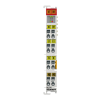
2. Separating the individual modules
2.1. Separating the power supply unit, the CX-System CPU and other components
Place the CX-block onto a suitable support with the front facing down. Then insert a flat screwdriver with
dimensions 1.0 x 5.5 x 150 mm into the locking mechanism, and then operating the slider by turning it about
90 degrees. The locking mechanism on the rear affects an approx. 2-3 mm wide clearance of the module
latching mechanism, pushing them apart. The plug connectors of the PC 104 interface can then be pulled
apart carefully.
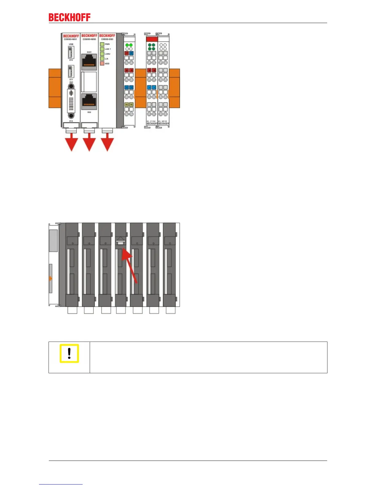
Only modules (CPU, fieldbus connections and UPS modules) that can be separated non-destructively
feature a release device. Modules that cannot be separated only feature a marking point (with or without red
paint seal). Applying force to these elements will destroy them.
Attention
Forcibly opening the module housing
Forcibly opening the module housing (e.g. removing the cover) will destroy the housing.
Disposal
The device must be fully dismantled in order to dispose of it.
Electronic parts must be disposed of in accordance with national electronics scrap regulations.
 Loading...