5
EUROPOWER EP1500/EP2500
2. CONTROL ELEMENTS
1.1.2 Initial operation
Please make sure the unit is provided with sufficient ventilation,
and never place your EUROPOWER amp on top of other heat-
emanating equipment or in the vicinity of a heater to avoid the risk
of overheating.
The mains connection is made via the enclosed power cord
and a standard IEC receptacle. It meets all international safety
certification requirements.
+ Please make sure that all units have a proper ground
connection. For your own safety, never remove or
disable the ground conductor from the unit or the
AC power cord.
1.1.3 Online registration
Please do remember to register your new BEHRINGER
equipment right after your purchase by visiting
www.behringer.com (alternatively www.behringer.de) and
kindly read the terms and conditions of our warranty carefully.
Should your BEHRINGER product malfunction, our goal is to
have it repaired as quickly as possible. To arrange for warranty
service, please contact the retailer from whom the equipment
was purchased. Should your BEHRINGER dealer not be located
in your vicinity, you may directly contact one of our subsidiaries.
Corresponding contact information is included in the original
equipment packaging (Global Contact Information/European
Contact Information). Should your country not be listed, please
contact the distributor nearest you. A list of distributors can be
found in the support area of our website (www.behringer.com).
Registering your purchase and equipment with us helps us
process your repair claims quicker and more efficiently.
Thank you for your cooperation!
ATTENTION!
+ We would like to bring your attention to the fact
that extremely loud sound levels may damage your
hearing as well as your loudspeakers. Please lower
both GAIN controls leftwards before powering up
the unit. Be sure to keep the volume at an
appropriate level.
2. CONTROL ELEMENTS
Since control elements of both the EP1500 and the EP2500 are identical, we have used the EP1500 as the model represented in the
illustrations to assure simplicity.
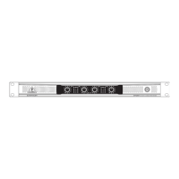
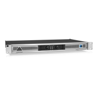
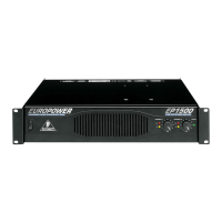
2.1 Front panel
Fig. 2.1: Front panel control elements
The main switch is used to power up the amp.
+ Please take note: Merely switching the unit off does
not mean that it is fully disconnected from the
mains. When not using the unit for prolonged
periods of time, please unplug the units power cord
from the power outlet.
Ventilation openings are located at the front of the unit, so
that hot air is prevented from being trapped inside the unit,
thus causing faulty operation or even damage.
The CLIP LED lights up when the signal is distorted. Should
distortion occur, reduce the input level, so that the CLIP
LED stops lighting up.
The SIGNAL LED lights up as long as a signal is present
at the input.
The GAIN control (channels 1 and 2) is used for setting
up the input gain.
The POWER LED lights up as soon as the unit is powered
up.
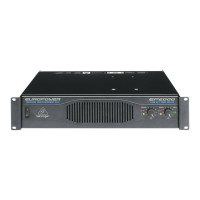
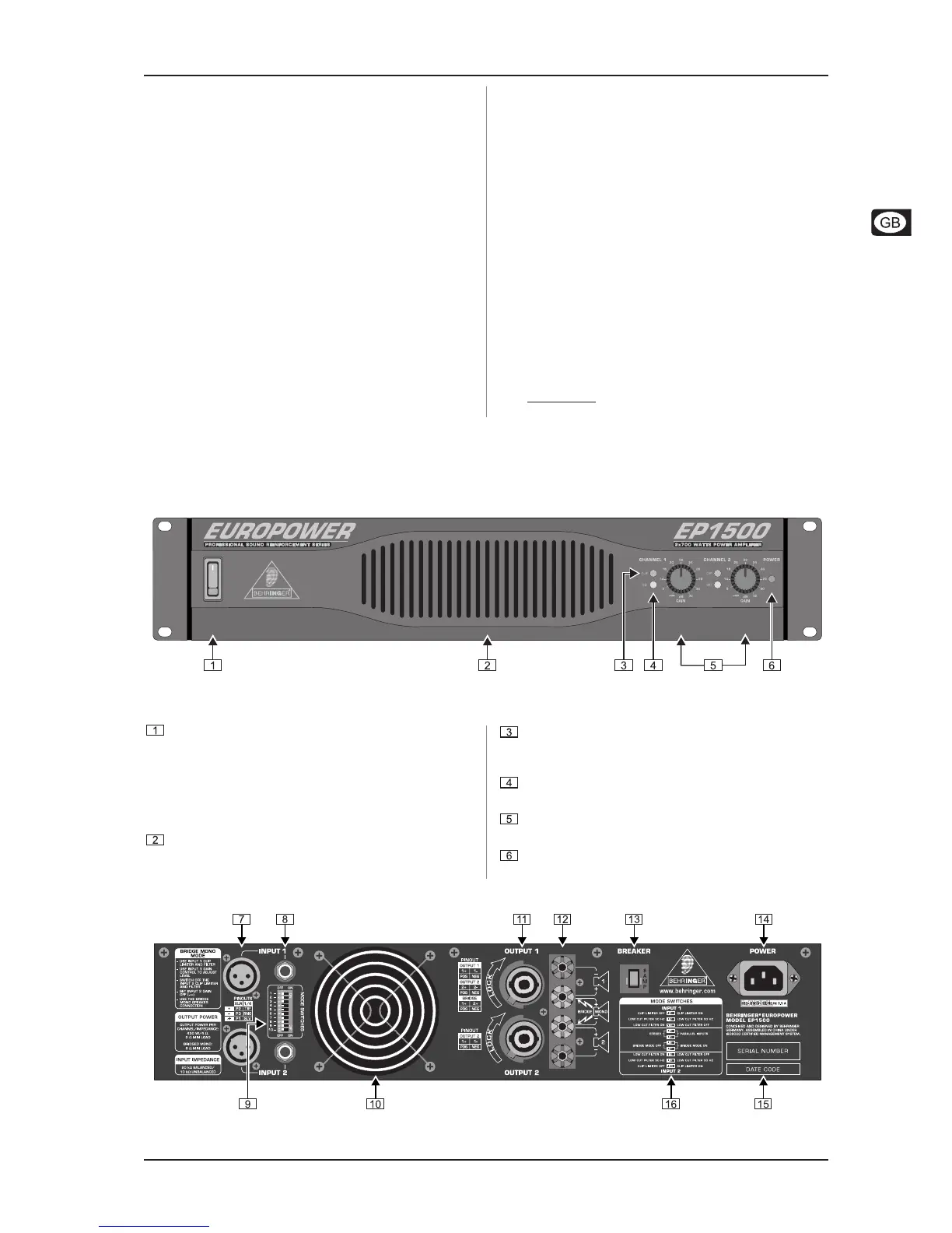
2.2 Rear panel
Fig. 2.2: Rear panel control elements
 Loading...